RL78/G15 CHAPTER 13 SERIAL INTERFACE IICA
R01UH0959EJ0110 Rev.1.10 Page 592 of 765
Mar 7, 2023
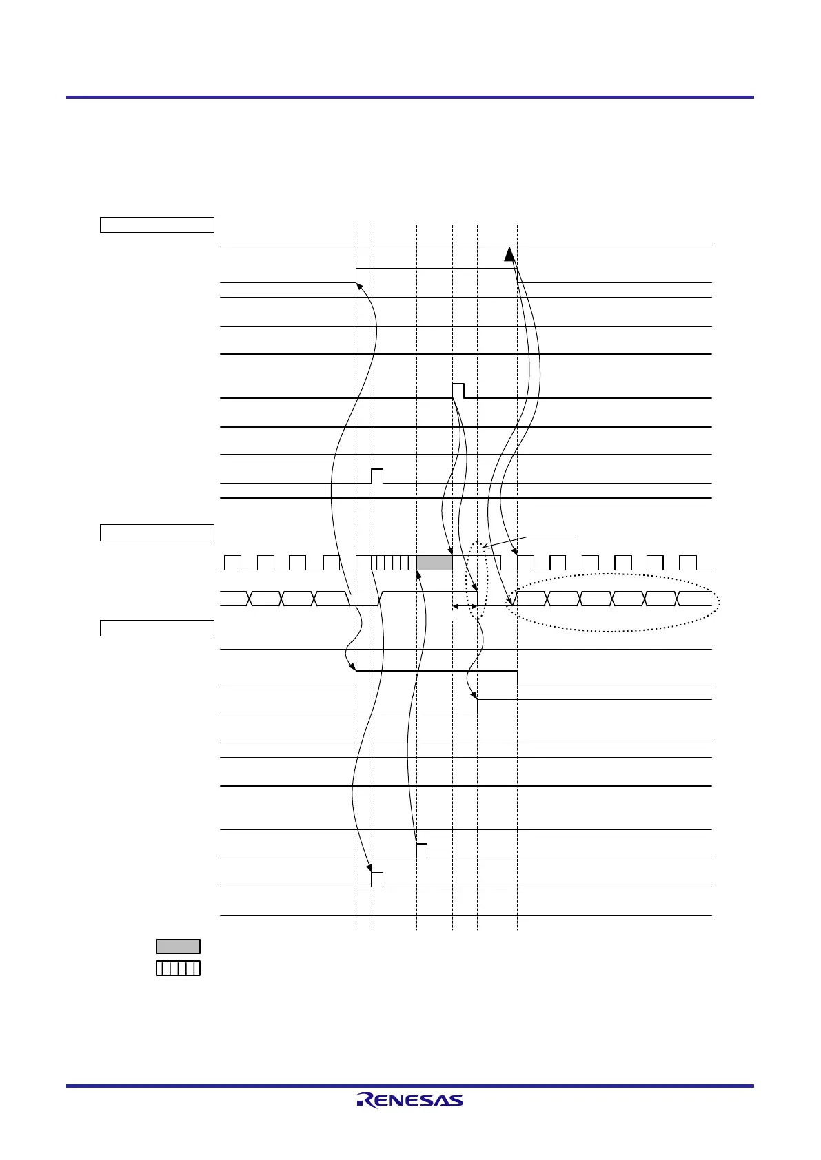
Figure 13-31. Example of Master to Slave Communications
(9th Cycle Clock Stretching is Selected for Both Master and Slave) (4/4)
(4) Data ~ restart condition ~ address
IICA0
ACKD
0
(
ACK detection
)
<
ii>
L
L
H
H
Master side
STT0
(
ST trigger)
SPT0
(
SP trigger)
WREL
0
(release clock stretching
)
INTIICA
0
(
interrupt)
TRC0
(transmission
/reception
)
Bus line
SCLA
0 (
bus)
(clock line)
SDAA0
(bus)
(data line
)
D
1
0 AD6
Slave side
IICA
0
ACKD0
(
ACK detection
)
<7>
H
H
L
L
Note 2
STD0
(ST detection
)
SPD0
(SP detection
)
WTIM
0
(
Clock stretch timing control)
ACKE0
(ACK control)
MSTS0
(communication state)
WREL0
(release clock stretching)
INTIICA
0
(
interrupt)
TRC0
(transmission/reception)
WTIM0
(
Clock stretch timing control)
ACKE
0
(
ACK control)
MSTS0
(
communication state)
Restart condition
D
1
1
D
1
2D
1
3
ACK
AD5 AD4
AD3 AD
2 AD1
H
H
L
<i>
<iii
>
<8>
Slave address
Note 1
: Clock stretching by the master
: Clock stretching by the master and slave
Note 1. Make sure that the time between the rise of the SCLA0 pin signal and the generation of the start condition
after a restart condition has been issued is at least 4.7 μs when standard mode is set and at least 0.6 μs
when fast mode is set.
 Loading...


