Malfunction and Remedies
Emergency operation ventilator drives emergency operation
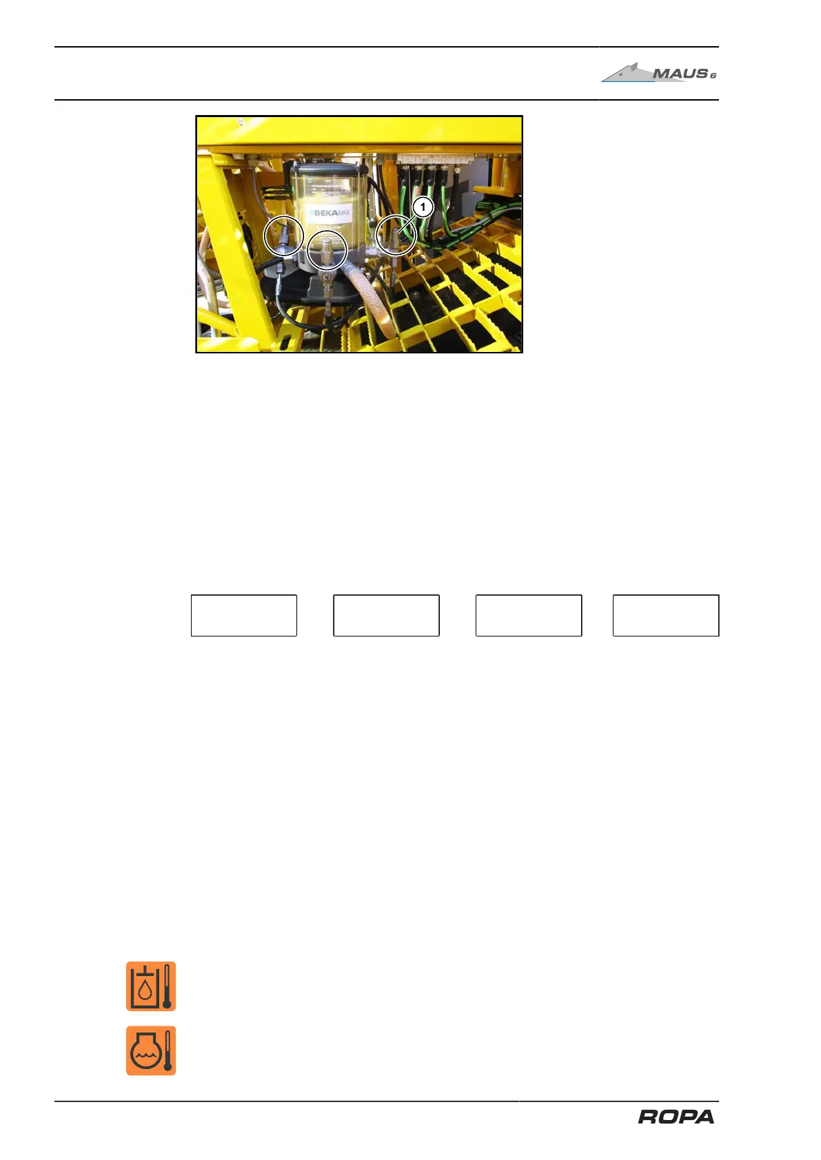
(1) Safety valve
– Search for the blocked spot in the pipe system. Go along the stiffer grease pipe
from the lubricating pump through the main distributor (the blocked pipe is stiffer
because it is under pressure) further to the corresponding sub-distributor and from
there to the blocked lubricating point. Please refer to chapter 9 for a detailed plan
(See Page 519).
– Disconnect the pipe from the distributor and screw a lubricating nipple into the cor-
responding (sub) distributor.
– Try to loosen the block strongly pressing grease into the distributor using the hand
lever grease gun.
– Proceed systematically: from the grease pump to the main distributor, from there to
the sub-distributor, etc..
Lubricat-
ing pump
→
Main distributor
→
Sub-distributor
→
Lubricat-
ing point
– Once you determine that the line is permeable again, connect the line with the con-
sumer. Check the free passage by performing an intermediate lubrication. (See
Page 323)
– Shouldn't the method prescribed here lead you to any success, please contact your
ROPA service station.
Some distributors are provided with a lubricating nipple. This lubricating nipple is used
to simplify troubleshooting.
All lubrication points of the sub-distributor can be supplied with grease via this lubricat-
ing nipple, because there is a check valve in the outlet of the main distributor.
There is no check valve between the lubrication pump and the main distributor.
The main distributors can be recognised by the integrated lifting pin indicator (See
Page 323). Should you feel only slight resistance when greasing the lubricating nip-
ple at the main distributor, then the grease can flow freely into the grease reservoir of
the central lubrication pump. In this case the wing in central lubrication pump must be
turned by approx. 120° via manual intermediate lubrication.
8.14 Emergency operation ventilator drives emergency operation
Emergency operation ventilator drives
To check whether the fan wheel of the cooling system is really running at maximum
speed, the plug (1) labelled "Y099" can be disconnected from the hydraulic pump for
test purposes. Then, the ventilator should be running at maximum speed.
If the cooling performance is not improved by this measure, then the machine may
only be operated at reduced load.
496 / 546