4 Installing Capillary Columns and Setting Analytical Flow Lines
4.1 Installation Location for Capillary Columns
48
GC-2014
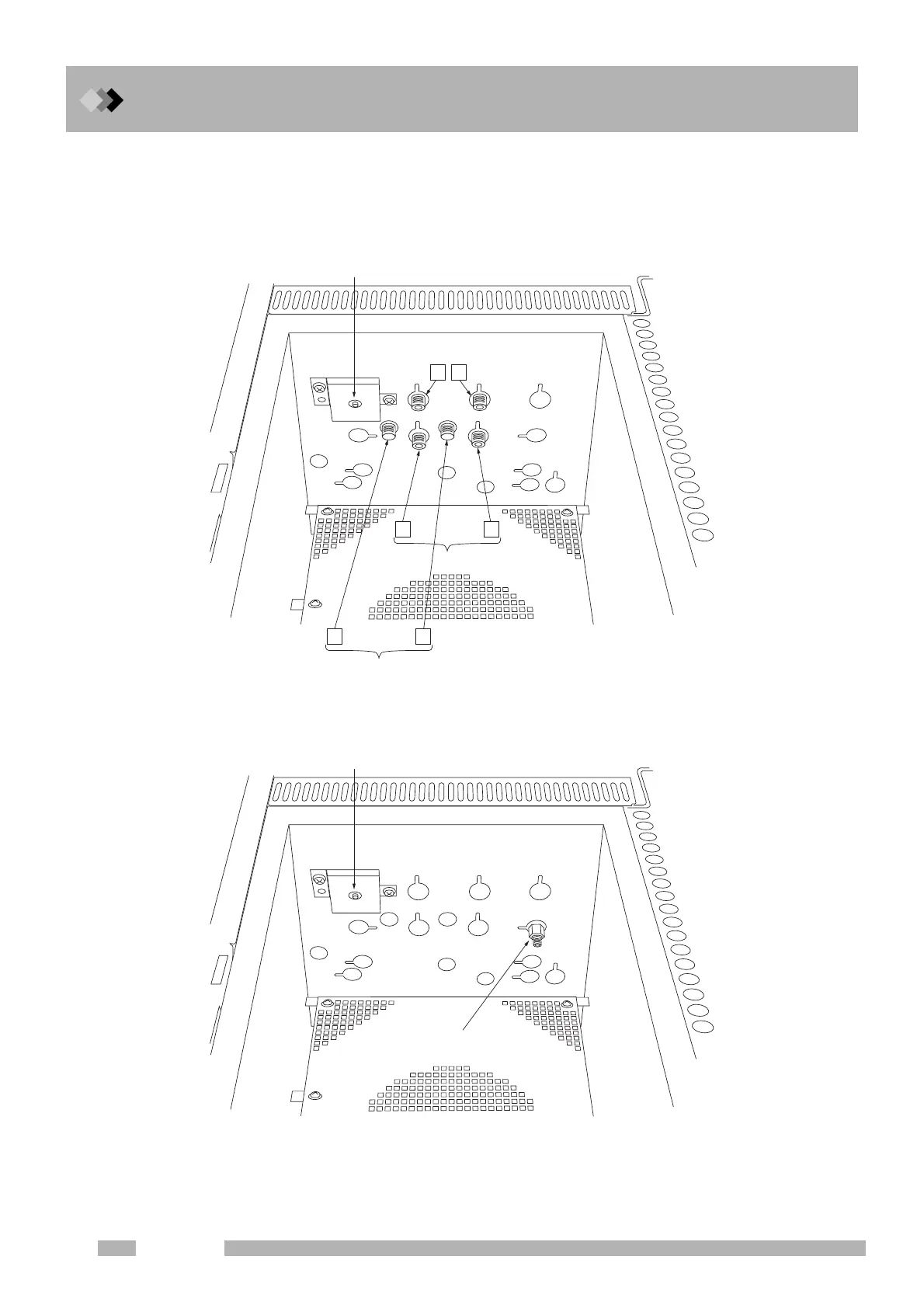
Check which units the joints found on the column oven correspond to.
Fig. 4.1.2 (a) and (b) show the layout for the GC-2014ATF+SPL model and GC-2014AFsc
model. Left and right sides viewed from the front of the unit are indicated as L (left) and R
(right) respectively.
Fig.4.1.2 (a) Column connecting joints (GC-2014ATF+SPL model)
Fig.4.1.2 (b) Column connecting joints (GC-2014AF
SC model)
SPL
Dual INJ
Dual FID
.4
.4
Dual TCD
.4
52.
Single FID

 Loading...


