8 Setting the Analytical Parameters and File Management
8.3
8.
98
GC-2014
8.3Specifying the Analytical Flow Line
Components ([Line Config])
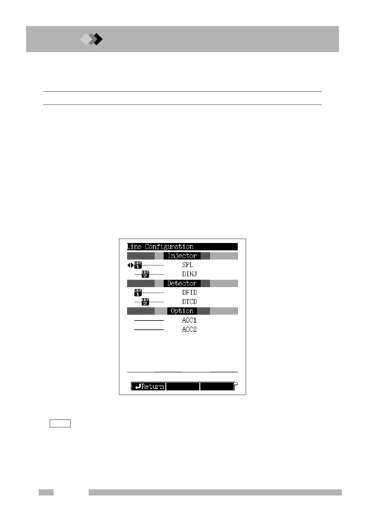
8.3.1 Screen description
Select [Line Confg] (PF menu) from the [SET] key main screen to display the Line Configu-
ration screen shown in Fig. 8.3.1.
The [SET] key main screen displays the parameters for one analytical flow line. The line
configuration screen determines the components (injection port, detector (s), and options) of
the analytical flow line.
When the system is turned on, the temperatures are controlled for the components in the
flow line. If the AFC is present, carrier gas is supplied to the specified injection port, If APC is
present, detector gases are supplied to the detector (s) specified, One injection port and up
to two detecotrs can be included in an analytical flow line, Temperatures are not controlled,
and gases are not supplied, to conponents which are not part of the analytical flow line.
The line configuration screen displays all the components installed. Move the cursor to the
desired component using the [ △ ] and [ ▽ ] keys. Use the [ ] and [ ] to specify the ana-
lytical flow line (1-4) to which the component belongs. Press [Enter] to validate the selection.
When two injection ports or two option units are selected for a same line, the previous unit
setting is cancelled.
“DINJ” is not displayed on the line configuration setup screen when “AMC.LR” is set for “DAFC unit” on
“OTHER CONFIGURATIONS” (16.6.11).
AUX temperature control, AUX APC, AUX AMC, manual flow controllers and dual AFC set to
“AMC.LR” can be set and controlled regardless to flow line configuration settings.
Fig. 8.3.1 Line configuration setup screen
△
△
NOTE

 Loading...


