61
5.1
5.5.
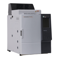
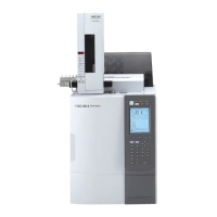
GC-2014
5 Analysis
5.1Analysis Flow Chart
For detailed descriptions about analysis procedures, refer to the operation manual.
5.1.1 Preparation
Injection port preparation Select an injection port suitable to the sample injection method.
Confirm that the septum and insert are properly attached.
Check dirt on the septum and the number of injections and replace it
when necessary (after approximately 100 injections).
Column preparation Attach the column to the injection port and detector correctly.
When the above preparations are complete, turn ON the GC (power switch on the lower
right side of the GC).
5.1.2 Setting Parameters
Set the column information
Set parameters on the [FLOW] key screen. Set the column inner diameter,
and the flow rates column length, and the film thickness on [Column] (PF menu). For
the SPL and WBL, set the purge flow rate on [Purge] as well.
(When the column flow rate is set by the AFC, changing the column
temperature changes the column flow rate.)
Set the temperature of the
Set the temperatures on the [INJ] and [DET] key screens. (If the detector
detector and the injection port is set to “Off,” turn it “On.”) When the APC is used, set hydrogen, air,
makeup gas, etc. from [DET Gas] (PF menu).
Set the COL temperature and From the screen of the [COL] key, set the column initial temperature
the temperature program and the temperature program. Temperature settings must be within
the allowable column and detector ranges.
Start GC control Press the [SYSTEM] key to display the main screen.
Press [Start GC] (PF menu) to start GC control.
Press the [MONIT] key, and ensure that the temperature of each
zone, the gas flow rate, the gas pressure, etc. are correct.
Set the detector From the screen of the [DET] key, set the range and the time filter
constant.
Ensure that the temperature of the detector is rising, then ignite the
FID or set the TCD current value.
When all parameters reach
their respective setup values, the STATUS indicator light
becomes green and the system is ready for analysis.
When the dual packed INJ is used, a monitor injection screen to show the inlet to be used
appears.
The default zero parameter, “Zero at Ready” zeroes the detector sig-
nal when the GC is ready.
 Loading...

