EasyManuals Logo

Shimadzu GC-2014 Instruction Manual

Shimadzu GC-2014
318 pages
To Next Page IconTo Next Page
To Previous Page IconTo Previous Page
Page #268 background imageLoading...
Page #268 background image
16 Special Functions
16.7 Service and Maintenance
256
GC-2014
16.7.3 INSTALLATION (POSITION)
16.7.3.1 Screen Description
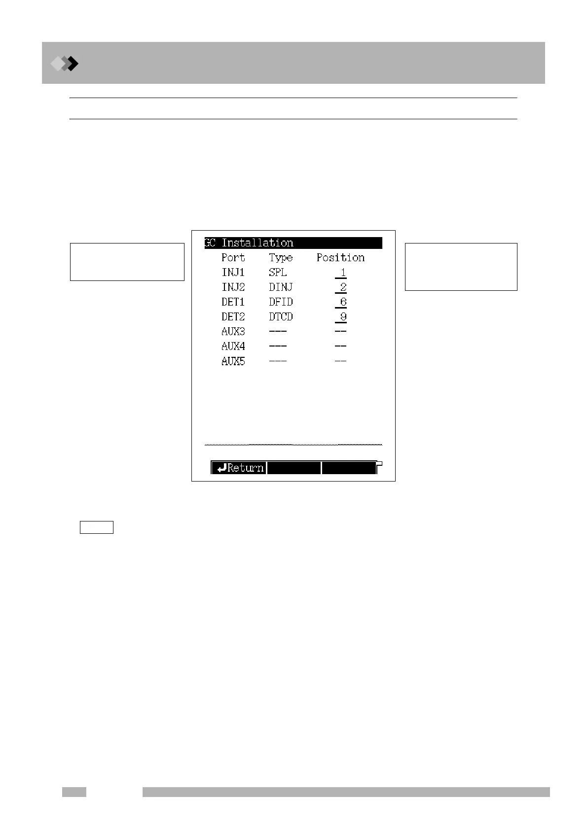
Select “7. SERVICE/MAINTENANCE” from the [FUNC] key screen, and then select “1.
INSTALLATION (POSITION)”, to open the GC installation screen shown in Fig. 16.7.2
appears.
After installing injection ports and detectors, specify the location of installed components
by entering the headed zone number while. referring to Fig. 16.7.3.
Set the left installation position for units with two column installation positions such as DINJ and DFID.
Fig. 16.7.2   GC installation setup screen
NOTE
Enter the heated zone number
to specify the unit installation
position in a number. (Refer
to Fig. 16.7.3.)
The component type of installed
injectors and detectors is
automatically determined.

Table of Contents

Other manuals for Shimadzu GC-2014

Questions and Answers:

Question and Answer IconNeed help?

Do you have a question about the Shimadzu GC-2014 and is the answer not in the manual?

Shimadzu GC-2014 Specifications

General IconGeneral
TypeGas Chromatograph
DisplayLCD
Maximum Heating Rate120°C/min
Data AcquisitionDigital
Maximum Number of Detectors4
WeightApprox. 45 kg
Carrier GasHelium, Nitrogen, Hydrogen
Detector OptionsFID, TCD, ECD, FPD
Injection PortSplit/Splitless, On-column
Gas ControlElectronic Flow Control (EFC)
Temperature Programming Rate0.1 to 120 °C/min
Power Requirements230 V AC, 50/60 Hz
Detector Temperature RangeUp to 400°C (depending on detector type)

Related product manuals