16 Special Functions
16.7 Service and Maintenance
258
GC-2014
16.7.4 INSTALLATION (PIPING)
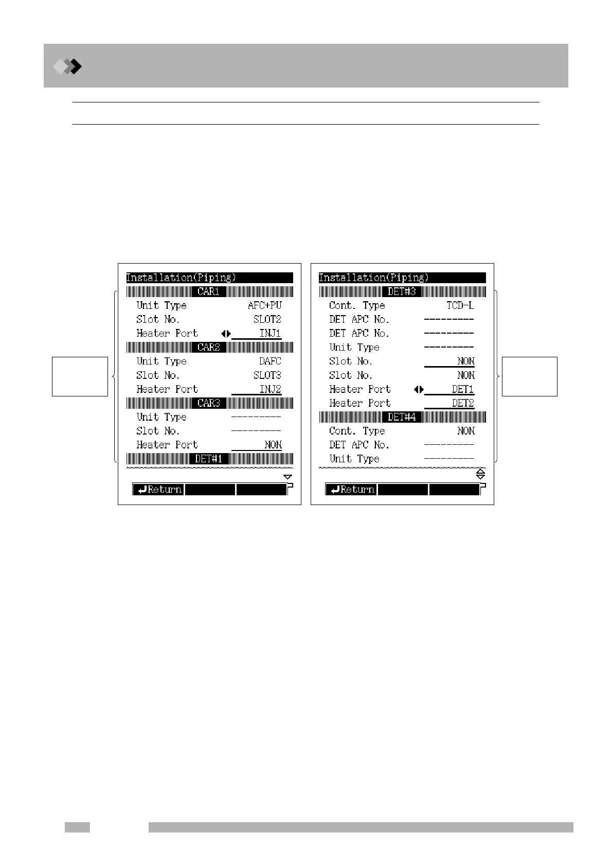
16.7.4.1 Screen description
Select “7. SERVICE/MAINTENANCE” from the [FUNC] key screen, and then select “2.
INSTALLATION (PIPING)”, to open the Installation (Piping) Screen shown in Fig.
16.7.4.
In the carrier gas, flow controller fields, specify where the flow controller injection port
tubing is connected.
In the detector gas flow controller fields, specify the detector configuration including
detector type and flow control unit.
16.7.4.2 Parameter list
Q Carrier gas flow controller settings
The names CAR1, CAR2 and CAR3 are automatically assigned in ascending order of
the slot No. for each installed AFC.
Specify the flow controller carrier gas settings for each CAR.
UNIT TYPE
For, display only.
When an AFC is installed, this is automatically displayed.
If a manual flow controller is installed, specify the installation Slot No.(See below.)
“SPLITTER” is automatically displayed for the Unit Type.
SLOT NO.
Selection: NON/MSLOT1−7, Default: NON
This item can be set only when a manual flow controller is installed.
Select the Slot No. where the manual flow controller is installed.
Slot No. which have already been set cannot be selected.
When an AFC is installed, its SLOT no. 2−6 is automatically recognized and displayed.
Fig. 16.7.4 Installation status setup screen
Detector gas
flow controller
settings
Carrier gas
flow controller
settings

 Loading...


