2 Before Use
2.2
2.
20
GC-2014
2.2
Outputting Analog Signals to the Chromatopac
GC-2014 can output analog signals for two channels, and detector signals to be outputted to
each channel can be set using keys. When a detector is changed, output can be changed
using keys without changing the connection on the back of the GC.
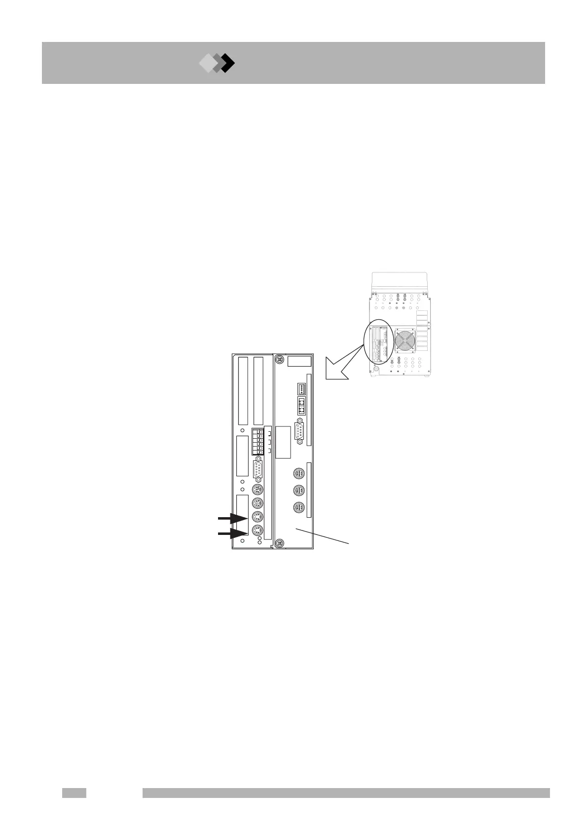
■ Connecting the Chromatopac signal cable
Connect the attached Chromatopac signal cable to the connector (ANALOG OUT1 or 2) on
the back of the GC. (Fig. 2.2.1)
Using this cable, analog signals can be outputted and the Chromatopac can be started when
the GC starts. (Refer to “16.6.9 Setting the link device code”)
ANALOG
OUT 2
ANALOG
OUT 1
AOC
INJECIOR1 INJECIOR2 SAMPLER
EVENT
OPTION
1
2
3
4
5
6
RS
-
232C
RS
-
232C OP1 LINKSTART
OUT/READY IN
START IN
READY OUT
AOC POWER SUPPLY
START OUT
Back of the GC
AOC built-in power source
NALOG OUT 1=Ch1
NALOG OUT 2=Ch2
Fig. 2.2.1 Connecting the Chromatopac signal cable

 Loading...


