10/00
4-53
Phaser 790/DocuColor 2006
REP 7.1, REP 7.2
Repairs and Adjustments
Initial Issue
REP 7.1 Size Switch PWB
Parts List on PL 3.1
Removal
WARNING
To avoid personal injury or shock, do not perform repair activities with the power switch
on or electrical power applied to the machine.
1. Switch off the machine power and disconnect the machine Power Cord.
2. Remove the Rear Cover Assembly. (REP 14.6)
3. Remove the LVPS. (REP 1.1)
CAUTION
The Size Switch Bracket and printer are connected by a harness. Handle the assembly care-
fully, to avoid damaging the harness.
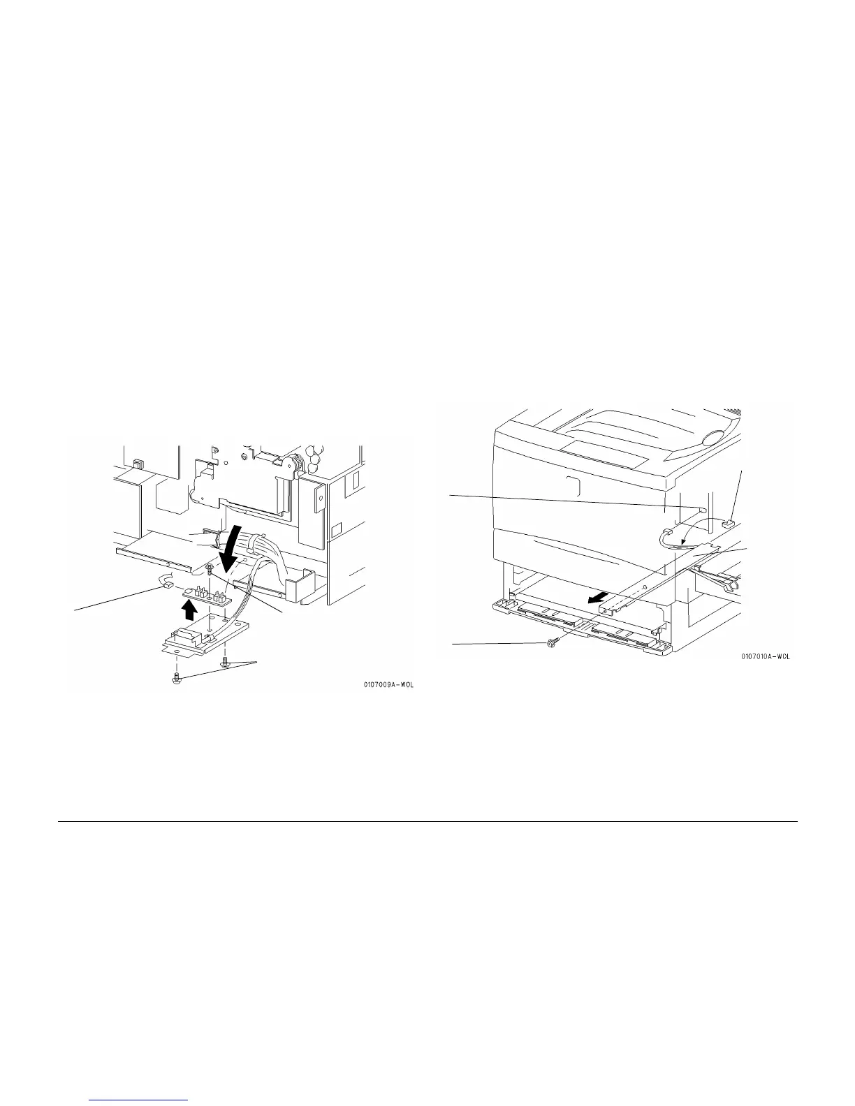
4. Remove the Size Switch Bracket. (Figure 1)
Figure 1 Removing the Size Switch PWB
Replacement
NOTE: Prior to replacement, partially pull out Tray 1 and (if present) the Duplex Tray.
1. Perform the procedure for removal in reverse.
2. Close Tray 1 and the Duplex Tray.
REP 7.2 Sensor Bracket
Parts List on PL 3.1
Removal
WARNING
To avoid personal injury or shock, do not perform repair activities with the power switch
on or electrical power applied to the machine.
1. Switch off the machine power and disconnect the machine Power Cord.
2. Remove the Tray 1 Assembly. (REP 7.6)
3. Remove the Front Mid Cover (REP 14.2) or the Duplex Tray Assembly (REP 8.27).
4. Remove the Sensor Bracket. (Figure 1)
Figure 1 Removing the Sensor Bracket
Replacement
1. Perform the procedure for removal in reverse.
NOTE: When installing dress the harness so it will not interfere with moving parts.
1
Remove the two screws securing
the Size Switch Bracket
2
Disconnect the Size
Switch connector
3
Remove the screw and then
remove the Size Switch PWB
1
Remove the screw securing the Sensor Bracket
4
Remove
the Sensor
Bracket
2
Disconnect
the connector
and release
the wires from
the wire clamp
on the frame
3
Release the
wires from
the clip