03/01
6-4
Phaser 790/DocuColor 2006
GP 2
General Procedures and Information
GP 2 Component Control (IOT)
The purpose of this procedure is to display the logic state of input signals and to energize out-
put components.
Procedure
Entering Component Control Mode
NOTE: Upon selecting a code, a time-out will occur after 30 seconds if no activity is sensed,
and the display will return to the root message.
1. Enter the Diagnostic Mode (GP 1).
2. Press the Menu button to scroll through the menu choices. The three choices to use for
component control are:
DI TEST - use this selection for diagnostic checks of digital input components.
DO TEST - use this selection for switching on the output components.
STOP DO TEST - use this selection for switching off the output components.
3. Press the Item Enter button to select the appropriate test mode.
4. Use the UP ARROW or DOWN ARROW in combination with the RIGHT ARROW and
LEFT ARROW buttons to select the Menu No. for the digital output test (Refer to the fol-
lowing tables for the available tests).
5. Press the Item Enter button to execute the test.
Stacking Codes
More than one component can be activated at a time. Multiple outputs codes can be stacked
(activated simultaneously), or a single input code can be activated in conjunction with one or
more output codes. Codes are activated sequentially; the input codes must be the last code
activated. when switching off components using the STOP DO TEST, components should be
deactivated in the sequence in which they were switched on.
Certain codes must be stacked, others cannot be stacked together. Refer to the following
tables for specific combination data.
Input Codes
NOTE: The component control function for Input Codes is not dynamically displayed.
You must first enter the code and validate the state. Next, actuate or deactuate the input
component, and then re-enter the code to check for a change of state.
The following table lists the digital input codes.
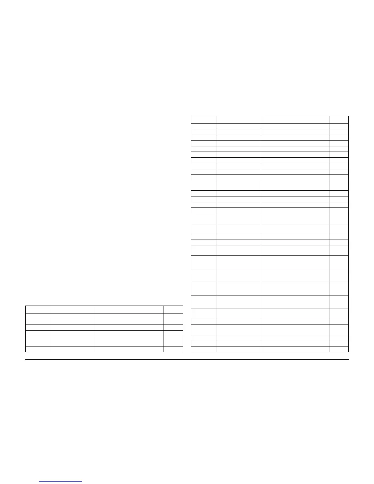
Table 1 Digital Input Codes
DI Code Component Signal BSD Ref
06 Feed Ready Not used --
15 Full Stack Sensor Top Tray Full (L) +5 VDC 10.4
16 Top Exit Sensor Sheet at Top Exit Sensor (L) +5 VDC 10.4
24 Fuser Entrance Sensor Sheet at Fuser Entrance (L) +5 VDC 10.1
25 Front Fuser Exit Sensor Sheet at Front Fuser Exit Sensor (L) +5
VDC
10.4
26 Sensor OHP MSI Not used --
27 OHP Sensor (Front) OHP Sensed (L) +5 VDC 8.6
28 OHP Sensor Rear Not used --
29 Registration Sensor Registration Sensed (L) +5 VDC 8.6
2A Bottom Plate Sensor Lift Plate Sensed (L) +5 VDC 7.2
2B Stack Height Sensor Stack Height Sensed (L) +5 VDC 7.2
2C Level Sensor Lift Plate Sensed (L) +5 VDC 7.2
35 ESS PWB Not used --
3B ESS PWB Not used --
42 TR0 Sensor TR0 Sensor On (L) +5 VDC 9.6
43 Rotary Sensor Home Sensed (H) +5 VDC 9.3
4B Rear Fuser Exit Sensor Sheet at Rear Fuser Exit Sensor (L) +5
VDC
10.4
50 ROS Assembly Not used --
51 Waste Toner Sensor Waste Toner Full (H) +5 VDC 9.9
52 Toner Box Sensor Toner Box Set (L) +5 VDC 9.9
53 MCU Check Not used --
54 MCU PWB (Dipswitch
S1)
Not used --
60 Tray No Paper Sensor
Tray 1
Tray No Paper Sensed (H) +5 VDC 7.1
61 Low Paper Switch Low Paper Sensed (L) +5 VDC 7.1
62 Fuser Assembly Fuser Installed (L) +5 VDC 1.2
66 Empty Sensor (Bypass
Tray)
Tray Empty Sensed (H) +5 VDC 7.2
67 Cartridge Sensor Cartridge Sensed (L) +5 VDC
NOTE: Stack with DO code 75
9.3
70 Fuser Motor Fuser Motor Fail (H) +5 VDC
NOTE: Stack with DO code 53
4.1
71 Paper Handling Motor Paper Handling Motor Fail (H) +5 VDC
NOTE: Stack with DO code 53
4.1
72 Process Drive Unit Process Motor Fail (H) +5 VDC
NOTE: Stack with DO code 54
9.2
73 Right Front Cover Inter-
lock
Right Front Cover Closed (L) +5 VDC 1.2
74 Exit Chute Interlock Exit Chute Closed (L) +5 VDC 1.3
75 Bypass Tray Guide
Switch
Bypass Guide Up (L) +5 VDC 7.2
76 BTR 2 Cam Sensor BTR 2 Cam Home (L) +5 VDC 9.8
77 Bypass Tray Interlock Bypass Tray Inserted (L) +5 VDC 1.3
80 Optional Sorter Not used --
Table 1 Digital Input Codes
DI Code Component Signal BSD Ref