10/00
4-54
Phaser 790/DocuColor 2006
REP 7.3, REP 7.4
Initial Issue
Repairs and Adjustments
REP 7.3 No Paper Sensor Assembly
Parts List on PL 3.1
Removal
WARNING
To avoid personal injury or shock, do not perform repair activities with the power switch
on or electrical power applied to the machine.
1. Switch off the machine power and disconnect the machine Power Cord.
2. Remove the Tray 1 Assembly. (REP 7.6)
3. Remove the Front Mid Cover (REP 14.2) or the Duplex Tray Assembly (REP 8.27).
4. Remove the Sensor Bracket. (REP 7.2)
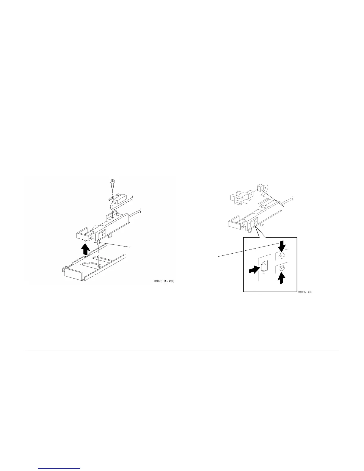
5. Remove the No Paper Sensor Assembly. (Figure 1)
Figure 1 Removing the No Paper Sensor Assembly
Replacement
1. Perform the procedure for removal in reverse.
REP 7.4 No Paper Sensor
Parts List on PL 3.1
Removal
WARNING
To avoid personal injury or shock, do not perform repair activities with the power switch
on or electrical power applied to the machine.
1. Switch off the machine power and disconnect the machine Power Cord.
2. Remove the Tray 1 Assembly. (REP 7.6)
3. Remove the Front Mid Cover (REP 14.2) or the Duplex Tray Assembly (REP 8.27).
4. Remove the Sensor Bracket. (REP 7.2)
5. Remove the No Paper Sensor Assembly. (REP 7.3)
6. Remove the No Paper Sensor. (Figure 1)
Figure 1 Removing the No Paper Sensor
Replacement
1. Perform the procedure for removal in reverse.
NOTE: When installing the No Paper Actuator, the Actuator must be positioned directly above
the No Paper Sensor.
1
Unhook the No Paper
Sensor Assembly from the
Sensor Bracket and
remove the assembly
2
Disconnect the
connector
1
Release the
locking tabs and
remove the No
Paper Sensor
from the Sensor
Bracket