10/00
4-153
Phaser 790/DocuColor 2006
ADJ 5.4, ADJ 6.1
Repairs and Adjustments
Initial Issue
Adjustment
CAUTION
If the screws on both the left and right-side Counterbalances are not loosened, the ADF Frame
will warp.
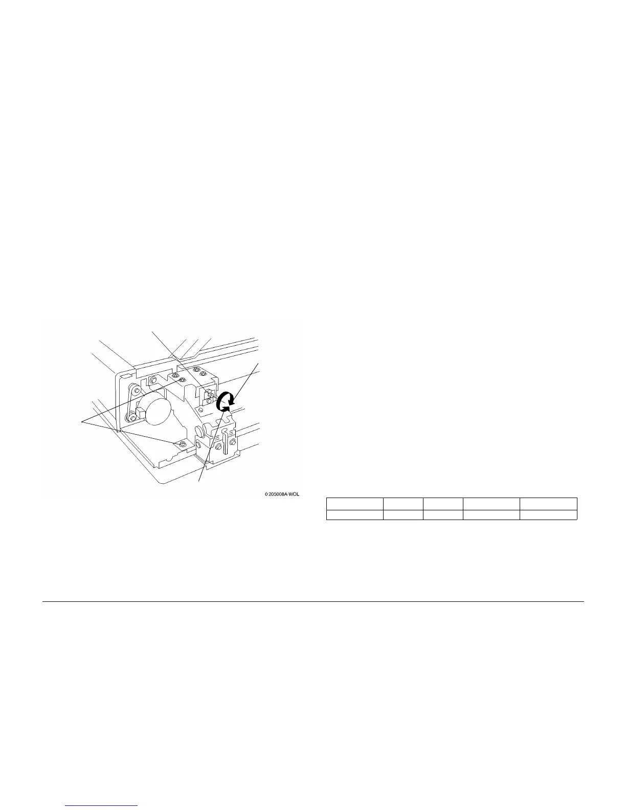
1. Loosen the screws at 6 places. (Figure 4)
2. Loosen the screws (2) used to mount the bottom of the left-side Counterbalance to the
ADF frame.
3. Rotate the adjustment screw on the right-side Counterbalance, to change the ADF posi-
tioning. (Figure 4)
• Direction “A”: ADF moves toward the rear
• Direction “B”: ADF moves toward the front
4. Tighten the screws in 6 locations, then tighten the two screws on the Left side of the
Counterbalance.
Figure 4 Adjusting Front-to-back Positioning
5. Repeat the checks and confirm that the measurement is within specification.
6. Place paper of each size in the ADF, make a test copy and check it for skew.
7. Perform the ADF Side Registration Adjustment. (ADJ 5.1)
ADJ 6.1 IIT Magnification
Purpose
The purpose is to achieve the correct magnification in the slow-scan direction (vertical) in
100% copy mode.
The following adjustments must be performed prior to performing this adjustment.
• Printer Registration (ADJ 8.1)
• ADF Side Registration (ADJ 5.1)
• ADF Lead Edge Registration (ADJ 5.2)
• IIT Lead Edge Registration (ADJ 6.3)
• IIT Side Registration (ADJ 6.4)
Check
1. Using the Copier Setup Test Pattern 82E8220, make two copies with the machine set to
Tray 1, 11x17 (A3), and 100% magnification.
2. Using the second copy from step 1, align the scale located at the middle of the copy with
the scale at the middle of the test pattern.
3. Verify that the 400mm increment on the copy matches the 400mm increment (±4.0mm)
on the test pattern.
Adjustment
1. Enter Diagnostic Mode (IIT) (GP 19).
2. Highlight Systemdata R/W and press the Select button.
3. Under Chain, enter 715 and then press the down arrow to highlight Link. Under Link,
enter 2. Press the Select button to display the Current dat values.
4. Change the values as required, based on the measurement results. When the measure-
ment is short, reduce the value; when the measurement is long, increase the value.
Change the values as follows:
NOTE: To enter a letter Hexadecimal value, press the asterisk key prior to entering each letter
value, then press the appropriate numerical key as follows: A=1, B=2, C=3, D=4, E=5,
F=6
a. Enter the new value and press Start.
b. Press the Select button to verify the value has changed.
5. Perform the check again.
Screws (6)
“A” Direction
“B” Direction
Adjustment
Screw
Table 1
Minimum Initial Maximum Remarks
Settings Range 0 23h 46h 0.1%/Step