10/00
4-162
Phaser 790/DocuColor 2006
ADJ 8.1, ADJ 9.1
Initial Issue
Repairs and Adjustments
Adjustment
1. Calculate the difference between the average measured value and the nominal values as
displayed in the Table 1.
2. Calculate the required adjustment value, allowing 1 unit increment to equal 0.17 mm of
change in top-to-bottom registration, or 0.50 mm of change in side-to-side registration.
3. Prepare to adjust the printer registration.
a. Enter the Diagnostic Mode (IOT) (GP 1).
b. Press the Menu button until IOT PARAM SET is displayed.
c. Press the Item Enter button.
d. Press the Up Arrow or Down Arrow button until CTRL VAL SET is displayed, then
press the Item Enter button.
e. Using the Up Arrow and Down Arrow buttons, select the Menu Number from the
Table 2.
f. Press the Item Enter button to display the current value of that parameter.
g. Using the Up Arrow and Down Arrow buttons, change the value as required.
h. Press the Item Enter button to write the new value.
i. Scroll the menu until DIAG EXIT is displayed, then press the Item Enter button.
j. Wait until the message PLEASE POWER OFF is displayed and then switch off and
switch on the power.
4. Perform the check again.
ADJ 9.1 Developer Spacing
Purpose
The purpose is to ensure that the Developer Housing is at the correct distance from the Copy/
Print Cartridge.
Check
WARNING
To avoid personal injury or shock, do not perform repair activities with the power switch
on or electrical power applied to the machine.
1. Switch off the machine power and disconnect the machine Power Cord.
2. Remove the Top Cover Assembly (REP 14.4).
3. Release the Rotary Latch. Turn the Rotary Frame clockwise until the magnetic roll of the
target Developer Housing is at the top. Continue to turn until the Rotary Latch catches in
the notch of the Rotary Frame.
CAUTION
Do not touch the surface (surface around circumference) of the white tracking roll with your fin-
gers while performing the following step. If you accidentally touch the surface of the tracking
roll with your fingers or if oily substances get on the surface, wipe the roll clean with a clean
cloth.
4. Clean the White Tracking Roll in front of the target Developer Assembly (in front of the
Magnetic Roll) with a clean cloth (Figure 1).
5. Make a mark on the White Tracking Roll, at the edge of the White Seal, in front of the tar-
get Developer Assembly (in front of the Magnetic Roll).
If a mark already exists on the White Tracking Roll, rotate the roll to align the mark with
the edge of the White Seal (Figure 1).
CAUTION
Turn the Rotary Frame as slowly as possible while performing the following step. Turning the
Rotary Frame too fast will produce a discrepancy in the amount of position change, thus mak-
ing it impossible to get an accurate reading. Visually inspect to make sure the black drum
flange and tracking roll touch each other while turning.
If you do not raise the lever of the Rotary Latch in the following step, the lever and tracking roll
will touch. This will allow the tracking roll to turn and you will not be able to accurately deter-
mine the amount of position change.
NOTE: The tracking roll is rotated when the black drum flange and tracking roll touch in the fol-
lowing step of the procedure.
6. Release the Rotary Latch which prevents the Developer Housing from turning. Turn the
Rotary Frame as slowly as possible 360 degrees (clockwise). This will allow you to mea-
sure how much the position has changed by how far the mark has moved from the edge
of the White Seal.
7. Check the Developer Spacing (Figure 1).
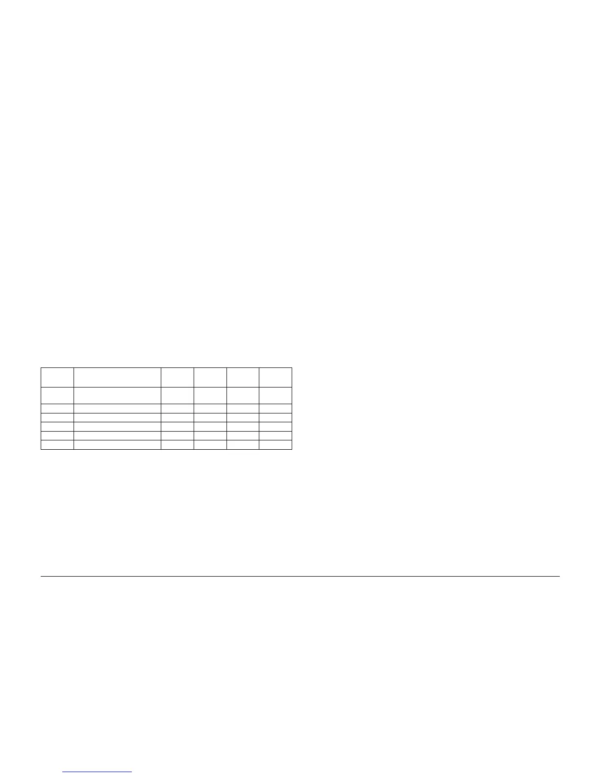
Table 2 Printer Registration Items for the Parameters
Menu No. Function
Default
Value
Maximum
Value
Minimum
Value Unit
11 Side-To-Side Registration 201 128 127 0.10 mm
16 Top-To-Bottom (Tray 1) 30 64 0 0.17 mm
17 Top-To-Bottom (Tray 2) 37 64 0 0.17 mm
18 Top-To-Bottom (Tray 3) 35 64 0 0.17 mm
19 Top-To-Bottom (Bypass Tray) 28 64 0 0.17 mm
1A Top-To-Bottom (Duplex Tray) 17 64 0 0.17 mm