5.2 European Standards
238 YASKAWA SIEPC71061705H GA700 Series Technical Manual
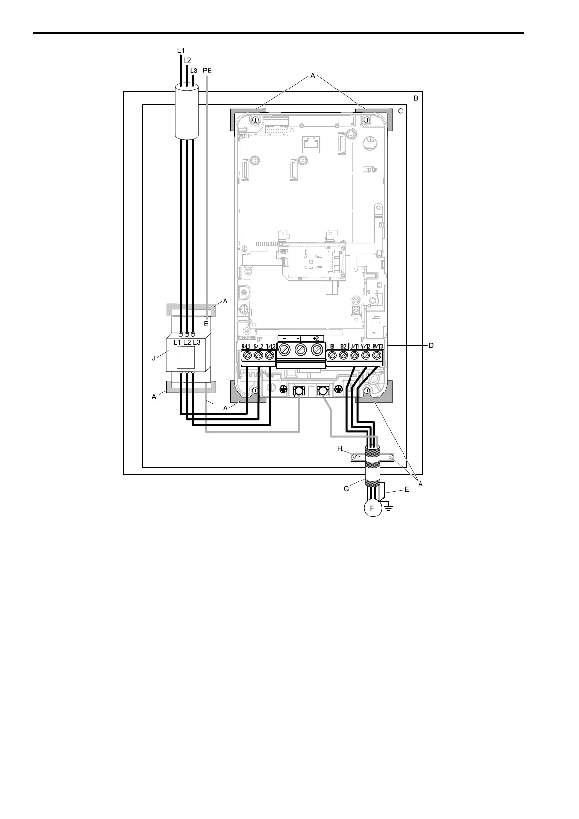
A - Grounding surface (Remove any paint or
sealant.)
B - Enclosure panel
C - Metal plate
D - Drive
E - Ground the shield.
F - Motor
G - Motor cable (Braided shield cable: 10 m (32.8 ft)
maximum)
H - Cable clamp
I - Grounding wire
J - EMC noise filter
Figure 5.17 EMC Noise Filter and Drive Installation Procedure
5. Connect the DC reactor to decrease harmonic distortion. Refer to DC Reactor on page 240 to select a DC
reactor.
Note:
• To maintain compliance with IEC/EN 61000-3-2 on drive models 2004, 2006, 4002, and 4004, install a DC reactor.
• Ground the DC reactor (option) on the back of the mounting base. Remove all paint from the mounting surface of the control
panel.
Ground Wiring
WARNING! Electrical Shock Hazard. Do not remove covers or touch circuit boards while the drive is energized. If you touch the
internal components of an energized drive, it can cause serious injury or death.
WARNING! Electrical Shock Hazard. Ground the neutral point on the power supply of drive models 2xxxB/C and 4xxxB/C to
comply with the EMC Directive before you turn on the EMC filter. If you turn ON the EMC filter, but you do not ground the neutral
point, it can cause serious injury or death.

 Loading...


