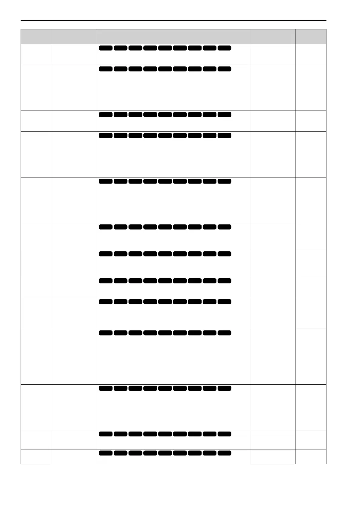
11.5 b: Application
486 YASKAWA SIEPC71061705H GA700 Series Technical Manual
No.
(Hex.)
Name Description
Default
(Range)
Ref.
b5-03
(01A7)
RUN
Integral Time (I)
Sets the integral time (I) that is applied to PID input.
1.0 s
(0.0 - 360.0 s)
674
b5-04
(01A8)
RUN
Integral Limit
Sets the upper limit for integral control (I) as a percentage of the Maximum Output
Frequency.
Note:
Parameter A1-02 [Control Method Selection] selects which parameter is the
maximum output frequency.
• A1-02 ≠ 8 [EZOLV]: E1-04 [Maximum Output Frequency]
• A1-02 = 8: E9-02 [Maximum Speed]
100.0%
(0.0 - 100.0%)
674
b5-05
(01A9)
RUN
Derivative Time (D)
Sets the derivative time (D) for PID control. This parameter adjusts system
responsiveness.
0.00 s
(0.00 - 10.00 s)
674
b5-06
(01AA)
RUN
PID Output Limit
Sets the maximum possible output from the PID controller as a percentage of the
Maximum Output Frequency.
Note:
Parameter A1-02 [Control Method Selection] selects which parameter is the
maximum output frequency.
• A1-02 ≠ 8 [EZOLV]: E1-04 [Maximum Output Frequency]
• A1-02 = 8: E9-02 [Maximum Speed]
100.0%
(0.0 - 100.0%)
674
b5-07
(01AB)
RUN
PID Offset Adjustment
Sets the offset for the PID control output as a percentage of the Maximum Output
Frequency.
Note:
Parameter A1-02 [Control Method Selection] selects which parameter is the
maximum output frequency.
• A1-02 ≠ 8 [EZOLV]: E1-04 [Maximum Output Frequency]
• A1-02 = 8: E9-02 [Maximum Speed]
0.0%
(-100.0 - +100.0%)
675
b5-08
(01AC)
RUN
Expert
PID Primary Delay Time
Constant
Sets the primary delay time constant for the PID control output. Usually it is not
necessary to change this setting.
0.00 s
(0.00 - 10.00 s)
675
b5-09
(01AD)
PID Output Level
Selection
Sets the polarity of the PID output.
0 : Normal Output (Direct Acting)
1 : Reverse Output (Reverse Acting)
0
(0, 1)
675
b5-10
(01AE)
RUN
PID Output Gain Setting
Sets the amount of gain to apply to the PID output.
1.00
(0.00 - 25.00)
675
b5-11
(01AF)
PID Output Reverse
Selection
Sets the function that enables and disables reverse motor rotation for negative PID
control output.
0 : Lower Limit is Zero
1 : Negative Output Accepted
0
(0, 1)
675
b5-12
(01B0)
Feedback Loss Detection
Select
Sets the drive response to PID Feedback Low/High. Sets drive operation after the drive
detects PID feedback Low/High.
0 : Digital Out Only, Always Detect
1 : Alarm + Digital Out, Always Det
2 : Fault + Digital Out, Always Det
3 : Digital Out Only, @ PID Enable
4 : Alarm + Digital Out, @PID Enable
5 : Fault + Digital Out, @PID Enable
0
(0 - 5)
676
b5-13
(01B1)
PID Feedback Loss
Detection Lvl
Sets the level that triggers PID Feedback Loss [FbL] detection as a percentage of the
Maximum Output Frequency.
Note:
Parameter A1-02 [Control Method Selection] selects which parameter is the
maximum output frequency.
• A1-02 ≠ 8 [EZOLV]: E1-04 [Maximum Output Frequency]
• A1-02 = 8: E9-02 [Maximum Speed]
0%
(0 - 100%)
676
b5-14
(01B2)
PID Feedback Loss
Detection Time
Sets the length of time that PID Feedback must be less than b5-13 [PID Feedback Loss
Detection Lvl] to detect PID Feedback Loss [FbL].
1.0 s
(0.0 - 25.5 s)
677
b5-15
(01B3)
PID Sleep Function Start
Level
Sets the output level that triggers the PID Sleep function.
Determined by A1-02
(0.0 - 590.0)
677

 Loading...


