Parameter Details
12
12.3 b: Application
YASKAWA SIEPC71061705H GA700 Series Technical Manual 651
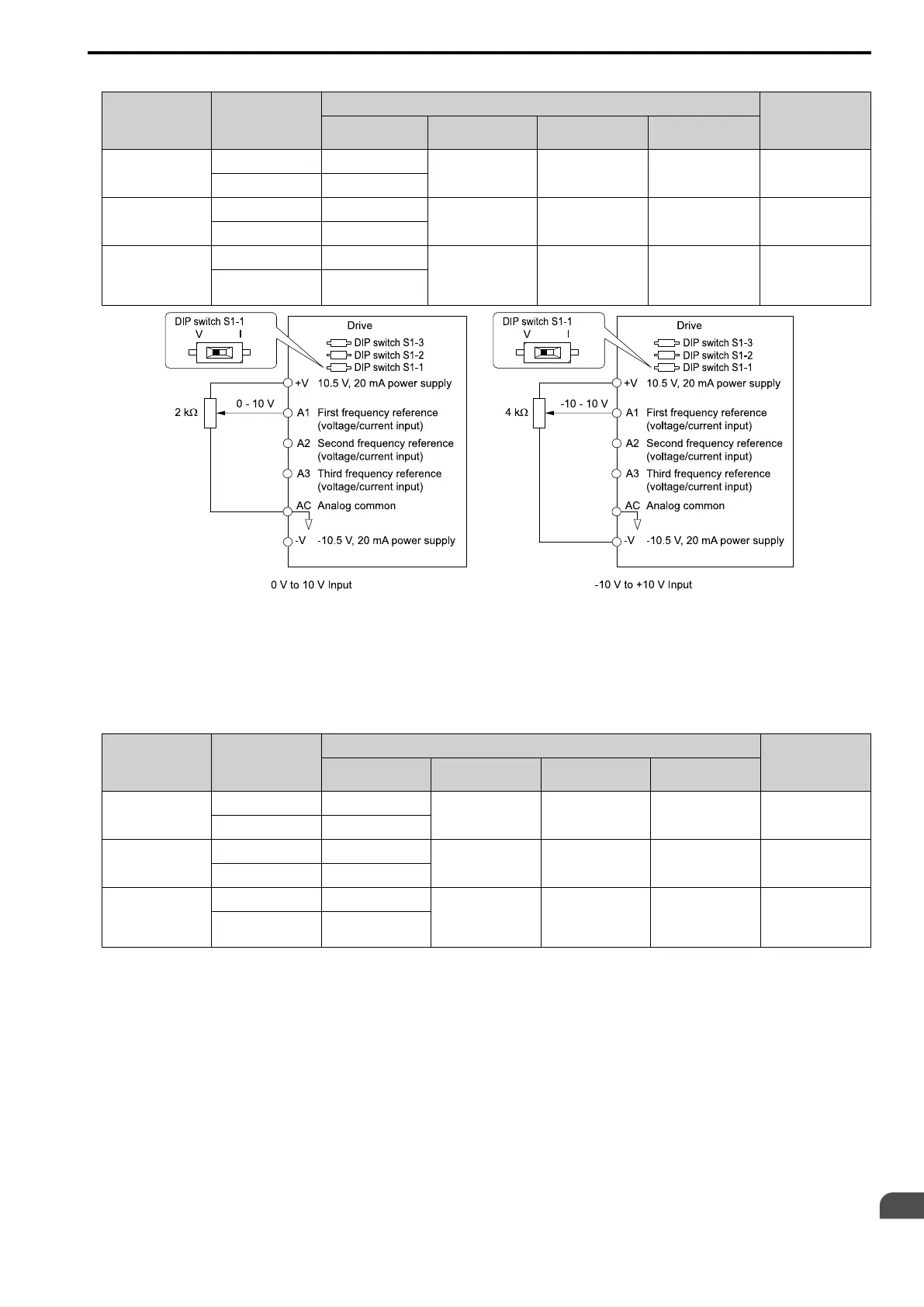
Table 12.24 Frequency Reference Voltage Input
Terminal
Terminal Signal
Level
Parameter Settings
Note
Signal Level
Selection
Function Selection Gain Bias
A1 0 - 10 V H3-01 = 0 H3-02 = 0
[Frequency Reference]
H3-03 H3-04 Set DIP switch S1-1 to
“V” for voltage input.
-10 - +10 V H3-01 = 1
A2 0 - 10 V H3-09 = 0 H3-10 = 0
[Frequency Reference]
H3-11 H3-12 Set DIP switch S1-2 to
“V” for voltage input.
-10 - +10 V H3-09 = 1
A3 0 - 10 V H3-05 = 0 H3-06 = 0
[Frequency Reference]
H3-07 H3-08 Set DIP switch S1-3 to
“V” for voltage input.
Set DIP switch S4 to
“AI” for analog input.
-10 - +10 V H3-05 = 1
Figure 12.23 Example of Setting the Frequency Reference with a Voltage Signal to Terminal A1
Note:
You can also use this diagram to wire terminals A2 and A3.
• Current Input
Refer to Table 12.25 to use a voltage signal input to one of the MFAI terminals.
Table 12.25 Frequency Reference Current Input
Terminal Signal Level
Parameter Settings
Note
Signal Level
Selection
Function Selection Gain Bias
A1 4 mA to 20 mA H3-01 = 2 H3-02 = 0
[Frequency Reference]
H3-03 H3-04 Set DIP switch S1-1 to
“I” for current input.
0 - 20 mA H3-01 = 3
A2 4 mA to 20 mA H3-09 = 2 H3-10 = 0
[Frequency Reference]
H3-11 H3-12 Set DIP switch S1-2 to
“I” for current input.
0 - 20 mA H3-09 = 3
A3 4 mA to 20 mA H3-05 = 2 H3-06 = 0
[Frequency Reference]
H3-07 H3-08 Set DIP switch S1-3 to
“I” for current input.
Set DIP switch S4 to
“AI” for analog input.
0 - 20 mA H3-05 = 3

 Loading...


