Parameter Details
12
12.8 H: Terminal Functions
YASKAWA SIEPC71061705H GA700 Series Technical Manual 823
Table 12.67 MEMOBUS MFDO Registers
Register number
(Hex.)
Name
15E0
bit0 MEMOBUS MFDO 1
bit1 MEMOBUS MFDO 2
bit2 MEMOBUS MFDO 3
Note:
• Refer to MFDO Setting Values on page 830 for more information about MFDO setting values.
• When you do not set functions to H2-40 to H2-42, set them to F.
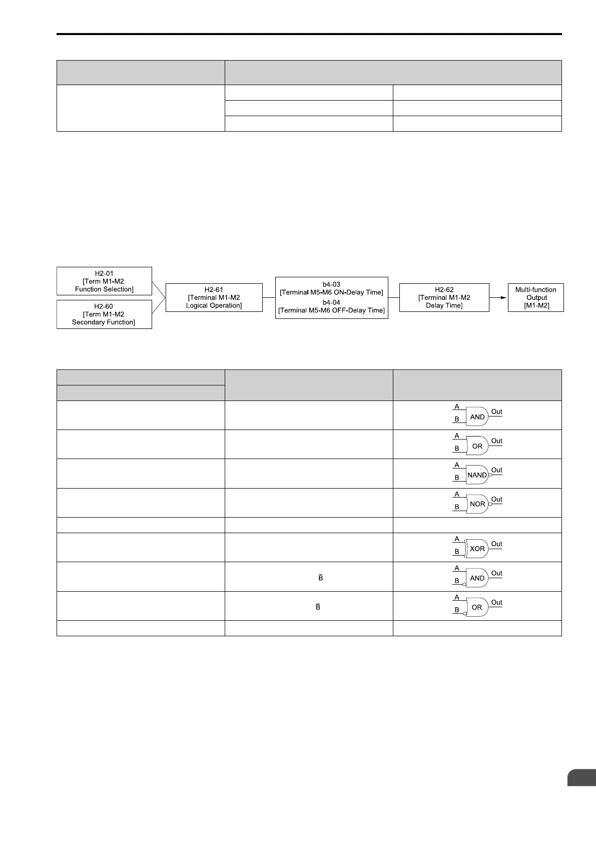
■ Output of Logical Operation Results of MFDO
This enables the logical operation results of two MFDOs to be output to one MFDO terminal.
Use H2-60, H2-63, and H2-66 [Term M1-M2 Secondary Function to Term M5-M6 Secondary Function] to set the
function of the output signal for which logical operations are performed.
Use H2-61, H2-64, H2-67 [Term M1-M2 Logical Operation to Term M5-M6 Logical Operation] to set the logical
operation.
Figure 12.90 Functional Block Diagram of Logical Operation Output for MFDO 1
Table 12.68 MFDO Logical Operation Table
Logical Operation Selection
Logical Operation Expression Logical Operation Notation
H2-61, H2-64, H2-67
0 A=B=1
1 A=1 or B=1
2 A=0 or B=0
3 A=B=0
4 A=B A=B
5 A != B
6
AND(A, )
7
OR(A, )
8 - On
Note:
• When you use the function to output logical calculation results, you cannot set H2-01 to H2-03 = 1xx [Inverse Output of xx]. If you do,
the drive will detect oPE33 [Digital Output Selection Error].
• When you do not use H2-60, H2-63, and H2-66, set them to F. The through mode function is not supported.

 Loading...


