Parameter Details
12
12.8 H: Terminal Functions
YASKAWA SIEPC71061705H GA700 Series Technical Manual 857
■ Calibrate Meters Connected to MFAO Terminals FM and AM
To calibrate the meters connected to terminals FM and AM, use these parameters:
• H4-02 [Terminal FM Analog Output Gain]
• H4-03 [Terminal FM Analog Output Bias]
• H4-05 [Terminal AM Analog Output Gain]
• H4-06 [Terminal AM Analog Output Bias]
Set these parameters where the output voltage of 10 V and output current of 20 mA are 100% of the signal level.
Use jumper switch S5 and H4-07 [Terminal FM Signal Level Select] or H4-08 [Terminal AM Signal Level Select]
to select the voltage output and current output.
No. Name Range Default
H4-02 Terminal FM Analog Output Gain -999.9 - +999.9% 100.0%
H4-03 Terminal FM Analog Output Bias -999.9 - +999.9% 0.0%
H4-05 Terminal AM Analog Output Gain -999.9 - +999.9% 50.0%
H4-06 Terminal AM Analog Output Bias -999.9 - +999.9% 0.0%
H4-07 Terminal FM Signal Level Select
0: 0 to 10 Vdc
1: -10 to +10 Vdc
2: 4 to 20 mA
0
H4-08 Terminal AM Signal Level Select
0: 0 to 10 Vdc
1: -10 to +10 Vdc
2: 4 to 20 mA
0
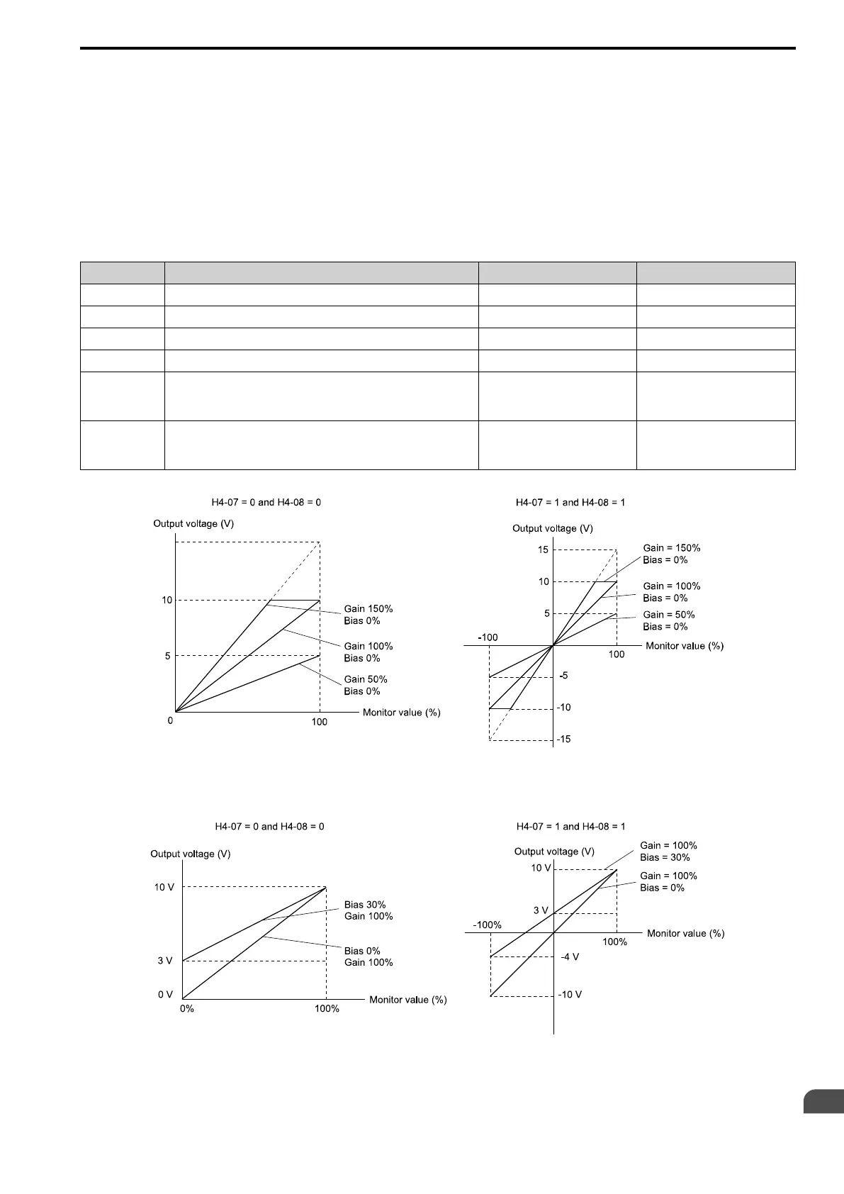
Figure 12.113 and Figure 12.114 show the gain and bias.
Figure 12.113 Analog Output Gain/Bias Configuration Example 1
For example, when the parameter value set to analog output is 0, and a 3 V signal is output to terminal FM, H4-03
[Terminal FM Analog Output Bias] is set to 30%.
Figure 12.114 Analog Output Gain/Bias Configuration Example 2
Calibrate Terminal FM
Stop the drive to calibrate meters. Use this procedure to calibrate:

 Loading...


