Chapter 6: I/O Features in Cyclone IV Devices 6–33
High-Speed I/O Standards Support
March 2016 Altera Corporation Cyclone IV Device Handbook,
Volume 1
A resistor network is required to attenuate the output voltage swing to meet RSDS,
mini-LVDS, and PPDS specifications when using emulated transmitters. You can
modify the resistor network values to reduce power or improve the noise margin.
The resistor values chosen must satisfy Equation 6–1.
1 Altera recommends that you perform simulations using Cyclone IV devices IBIS
models to validate that custom resistor values meet the RSDS, mini-LVDS, or PPDS
requirements.
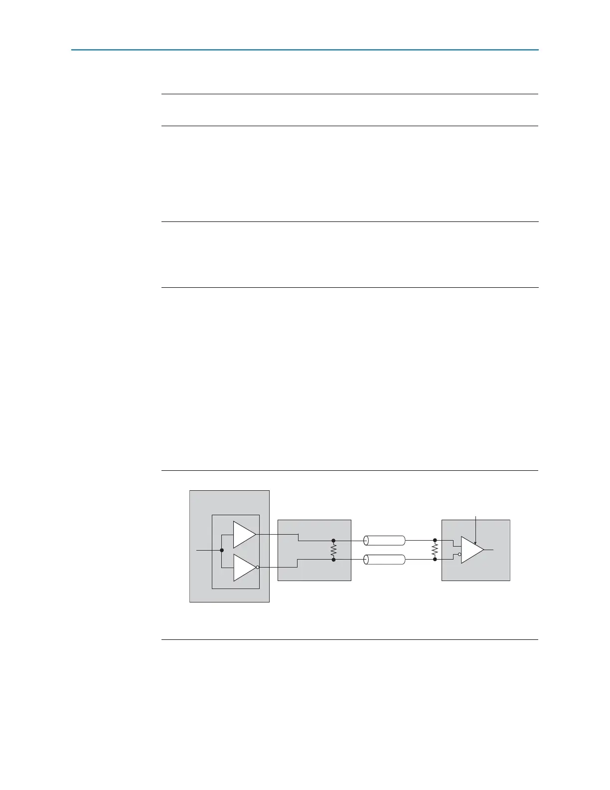
It is possible to use a single external resistor instead of using three resistors in the
resistor network for an RSDS interface, as shown in Figure 6–17. The external
single-resistor solution reduces the external resistor count while still achieving the
required signaling level for RSDS. However, the performance of the single-resistor
solution is lower than the performance with the three-resistor network.
Figure 6–17 shows the RSDS interface with a single resistor network on the top and
bottom I/O banks.
Note to Figure 6–16:
(1) R
S
and R
P
values are pending characterization.
Equation 6–1. Resistor Network
Figure 6–16. RSDS, Mini-LVDS, or PPDS Interface with External Resistor Network on the Top and
Bottom I/O Banks
(1)
R
S
R
P
2
-------
R
S
R
P
2
-------
+
------- -------------
50 =
Figure 6–17. RSDS Interface with Single Resistor Network on the Top and Bottom I/O Banks
(1)
Note to Figure 6–17:
(1) R
P
value is pending characterization.
RSDS Receiver
100 Ω
50 Ω
Cyclone IV Device
Single Resistor Network
Emulated
RSDS Transmitter
R
P
50 Ω