Chapter 1: Cyclone IV Transceivers Architecture 1–19
Receiver Channel Datapath
February 2015 Altera Corporation Cyclone IV Device Handbook,
Volume 2
Bit-Slip Mode
In bit-slip mode, the
rx_bitslip
port controls the word aligner operation. At every
rising edge of the
rx_bitslip
signal, the bit-slip circuitry slips one bit into the
received data stream, effectively shifting the word boundary by one bit. When the
received data after bit-slipping matches the programmed word alignment pattern, the
rx_patterndetect
signal is driven high for one parallel clock cycle.
1 You can implement a bit-slip controller in the user logic that monitors either the
rx_patterndetect
signal or the receiver data output (
rx_dataout
), and controls the
rx_bitslip
port to achieve word alignment.
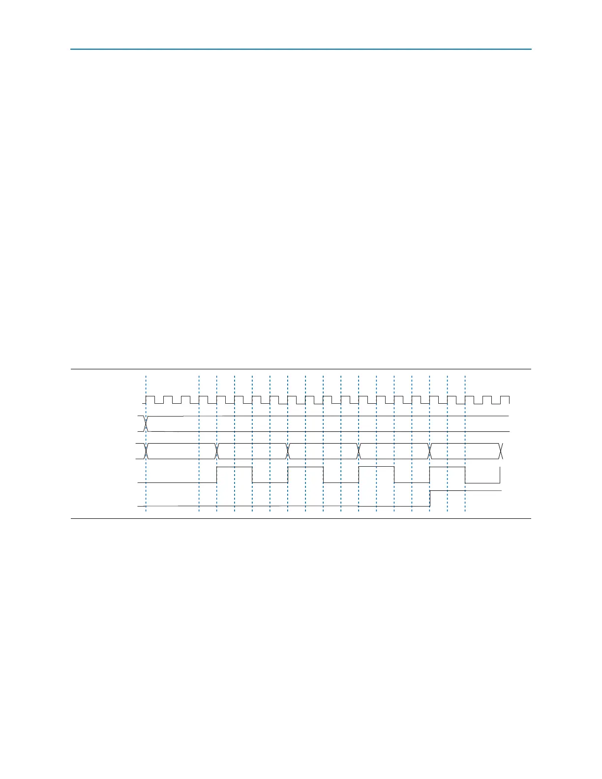
Figure 1–18 shows an example of the word aligner configured in bit-slip mode. For
this example, consider that 8'b11110000 is received back-to-back and
16'b0000111100011110 is specified as the word alignment pattern. A rising edge on the
rx_bitslip
signal at time n + 1 slips a single bit 0 at the MSB position, forcing the
rx_dataout
to 8'b01111000. Another rising edge on the
rx_bitslip
signal at time n + 5
forces rx_dataout to 8'b00111100. Another rising edge on the
rx_bitslip
signal at time
n + 9 forces
rx_dataout
to 8'b00011110. Another rising edge on the
rx_bitslip
signal
at time n + 13 forces the
rx_dataout
to 8'b00001111. At this instance,
rx_dataout
in
cycles n + 12 and n + 13 is 8'b00011110 and 8'b00001111, respectively, which matches
the specified 16-bit alignment pattern 16'b0000111100011110. This results in the
assertion of the
rx_patterndetect
signal.
Automatic Synchronization State Machine Mode
In automatic synchronization state machine mode, the word aligner achieves
synchronization after receiving a specific number of synchronization code groups,
and falls out of synchronization after receiving a specific number of erroneous code
groups. This mode provides hysteresis during link synchronization, which is required
by protocols such as PCIe, GbE, XAUI, and Serial RapidIO.
1 This mode is only supported using the 8B/10B encoded data with 10-bit input to the
word aligner.
Figure 1–18. Word Aligner Configured in Bit-Slip Mode
01111000
n
11110000
00111100 00011110 00001111
rx_clkout
rx_datain7..0]
rx_dataout[7..0]
rx_bitslip
rx_patterndetect
11110000
n + 1 n + 2 n + 3 n + 4 n + 5 n + 6 n + 7 n + 8 n + 9 n + 10 n + 11 n + 12 n + 13 n + 14