1–30 Chapter 1: Cyclone IV Transceivers Architecture
Transceiver Clocking Architecture
Cyclone IV Device Handbook, February 2015 Altera Corporation
Volume 2
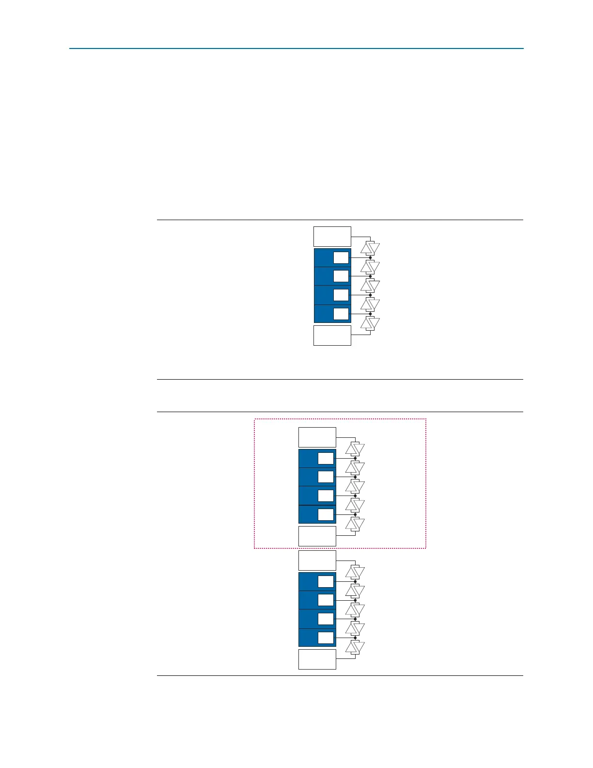
The CDR unit in each receiver channel gets the CDR clocks from one of the two
multipurpose PLLs directly adjacent to the transceiver block. The CDR clocks
distribution network is segmented by bidirectional tri-state buffers as shown in
Figure 1–29 and Figure 1–30. This requires the CDR clocks from either one of the two
multipurpose PLLs to drive a number of contiguous segmented paths to reach the
intended receiver channel. Interleaving the CDR clocks from the two multipurpose
PLLs is not supported.
For example, based on Figure 1–29, a combination of
MPLL_1
driving receiver channels
0, 1, and 3, while
MPLL_2
driving receiver channel 2 is not supported. In this case, only
one multipurpose PLL can be used for the receiver channels.
Figure 1–29. CDR Clocking for Transceiver Channels in F324 and Smaller Packages
Note to Figure 1–29:
(1) Transceiver channels 2 and 3 are not available for devices in F169 and smaller packages.
Figure 1–30. CDR Clocking for Transceiver Channels in F484 and Larger Packages
Transceiver
Block
GXBL0
CDR
clocks
MPLL_2
CDR
CDR
CDR
CDR
Ch3
(1)
MPLL_1
Ch2
(1)
Ch1
Ch0
Not applicable in
F484 package
Transceiver
Block
GXBL1
CDR
clocks
MPLL_8
CDR
CDR
CDR
CDR
MPLL_7
Ch1
Ch0
Transceiver
Block
GXBL0
CDR
clocks
MPLL_6
CDR
CDR
CDR
CDR
Ch3
MPLL_5
Ch2
Ch3
Ch2
Ch1
Ch0