Chapter 1: Cyclone IV Transceivers Architecture 1–51
Transceiver Functional Modes
February 2015 Altera Corporation Cyclone IV Device Handbook,
Volume 2
■ transmitter in electrical idle
■ receiver signal detect
■ receiver spread spectrum clocking
Low-Latency PCS Operation
When configured in low-latency PCS operation, the following blocks in the
transceiver PCS are bypassed, resulting in a lower latency PCS datapath:
■ 8B/10B encoder and decoder
■ word aligner
■ rate match FIFO
■ byte ordering
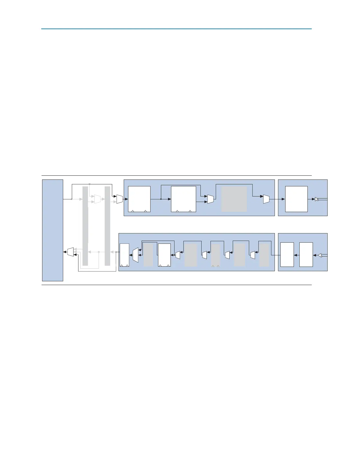
Figure 1–47 shows the transceiver channel datapath in Basic mode with low-latency
PCS operation.
.
Transmitter in Electrical Idle
The transmitter buffer supports electrical idle state, where when enabled, the
differential output buffer driver is tri-stated. During electrical idle, the output buffer
assumes the common mode output voltage levels. For details about the electrical idle
features, refer to “PCI Express (PIPE) Mode” on page 1–52.
1 The transmitter in electrical idle feature is required for compliance to the version 2.00
of PHY Interface for the PCI Express (PIPE) Architecture specification for PCIe
protocol implementation.
Signal Detect at Receiver
Signal detect at receiver is only supported when 8B/10B encoder/decoder block is
enabled.
Figure 1–47. Transceiver Channel Datapath in Basic Mode with Low-Latency PCS Operation
Byte Serializer
Transmitter Channel PCS Transmitter Channel PMA
Serializer
PCIe Hard IP
FPGA
Fabric
PIPE Interface
Tx Phase
Comp
FIFO
tx_dataout
wr_clk rd_clk wr_clk rd_clk
Receiver Channel PCS Receiver Channel PMA
rx_datain
Deserial-
izer
CDR
Byte
De-
serializer
Byte
Order-
ing
Deskew
FIFO
8B/10B
Decoder
Rate
Match
FIFO
Word
Aligner
Rx
Phase
Comp
FIFO
8B/10B Encoder