3–2 Chapter 3: Memory Blocks in Cyclone IV Devices
Overview
Cyclone IV Device Handbook, November 2011 Altera Corporation
Volume 1
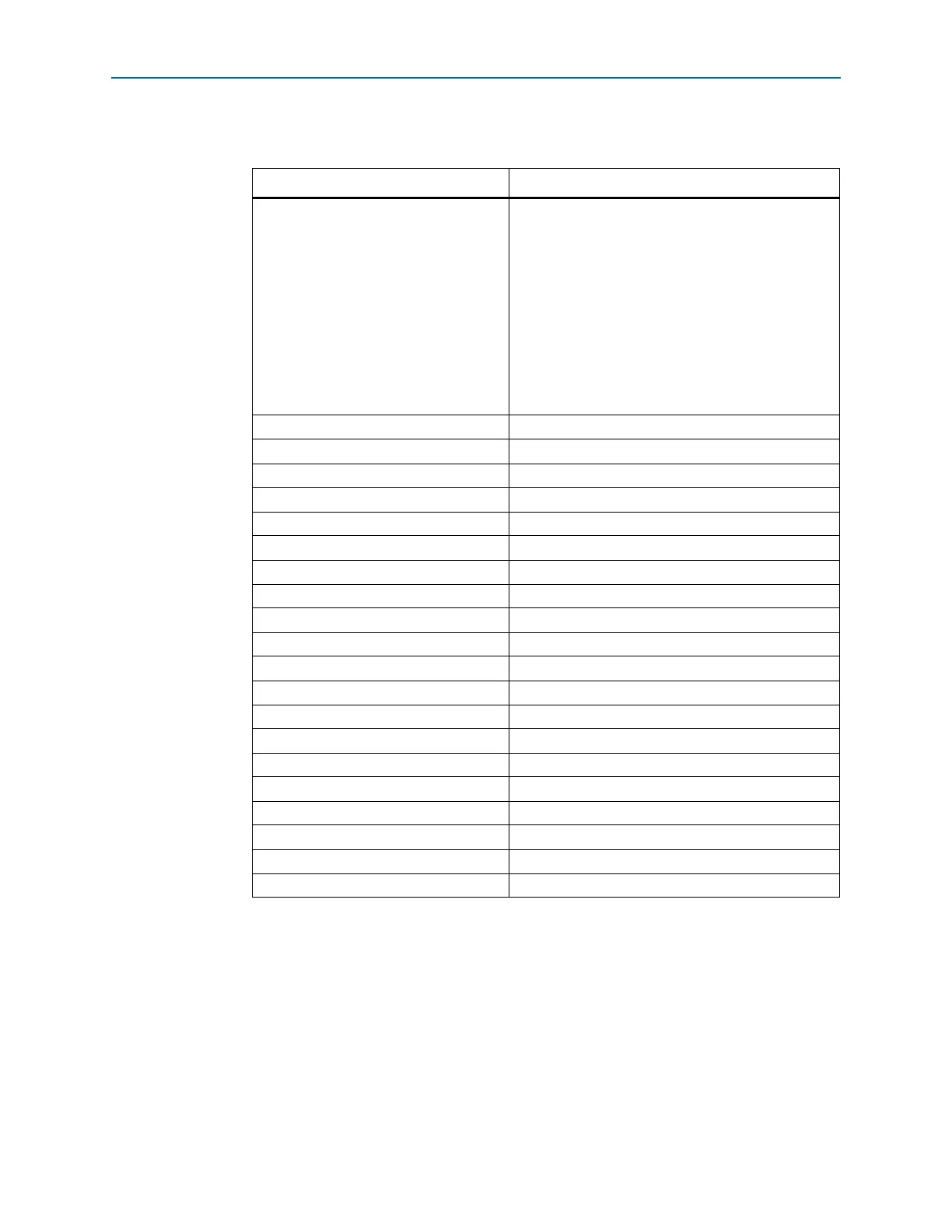
Tab le 3 –1 lists the features supported by the M9K memory.
f For information about the number of M9K memory blocks for Cyclone IV devices,
refer to the Cyclone IV Device Family Overview chapter in volume 1 of the Cyclone IV
Device Handbook.
Table 3–1. Summary of M9K Memory Features
Feature M9K Blocks
Configurations (depth × width)
8192 × 1
4096 × 2
2048 × 4
1024 × 8
1024 × 9
512 × 16
512 × 18
256 × 32
256 × 36
Parity bits v
Byte enable v
Packed mode v
Address clock enable v
Single-port mode v
Simple dual-port mode v
True dual-port mode v
Embedded shift register mode
(1)
v
ROM mode v
FIFO buffer
(1)
v
Simple dual-port mixed width support v
True dual-port mixed width support
(2)
v
Memory initialization file (.mif) v
Mixed-clock mode v
Power-up condition Outputs cleared
Register asynchronous clears Read address registers and output registers only
Latch asynchronous clears Output latches only
Write or read operation triggering Write and read: Rising clock edges
Same-port read-during-write Outputs set to Old Data or New Data
Mixed-port read-during-write Outputs set to Old Data or Don’t Care
Notes to Table 3–1:
(1) FIFO buffers and embedded shift registers that require external logic elements (LEs) for implementing control
logic.
(2) Width modes of ×32 and ×36 are not available.