1–4 Chapter 1: Cyclone IV Device Datasheet
Operating Conditions
Cyclone IV Device Handbook, December 2016 Altera Corporation
Volume 3
Recommended Operating Conditions
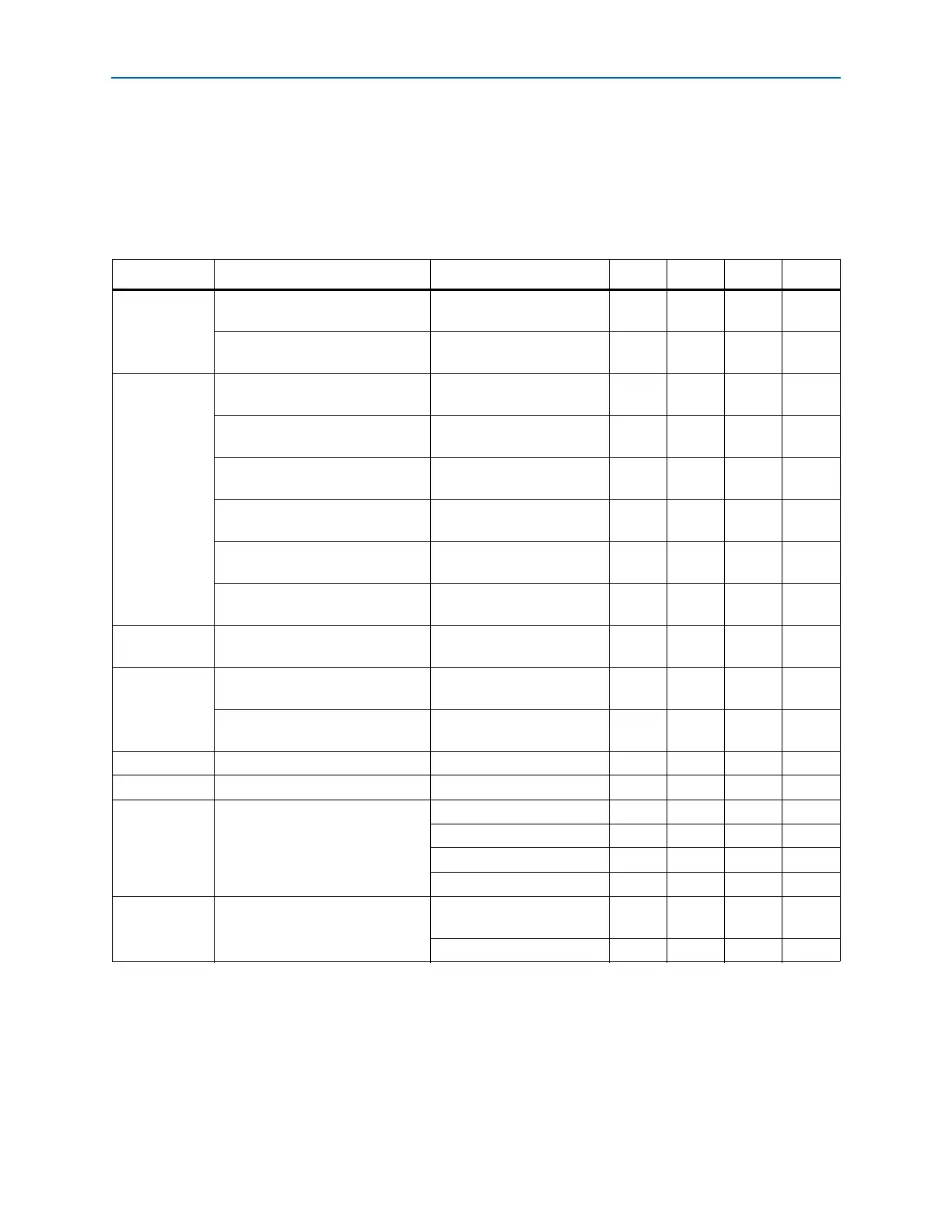
This section lists the functional operation limits for AC and DC parameters for
Cyclone IV devices. Table 1–3 and Table 1–4 list the steady-state voltage and current
values expected from Cyclone IV E and Cyclone IV GX devices. All supplies must be
strictly monotonic without plateaus.
Table 1–3. Recommended Operating Conditions for Cyclone IV E Devices
(1),
(2)
(Part 1 of 2)
Symbol Parameter Conditions Min Typ Max Unit
V
CCINT
(3)
Supply voltage for internal logic,
1.2-V operation
— 1.15 1.2 1.25 V
Supply voltage for internal logic,
1.0-V operation
— 0.97 1.0 1.03 V
V
CCIO
(3),
(4)
Supply voltage for output buffers,
3.3-V operation
— 3.135 3.3 3.465 V
Supply voltage for output buffers,
3.0-V operation
— 2.85 3 3.15 V
Supply voltage for output buffers,
2.5-V operation
— 2.375 2.5 2.625 V
Supply voltage for output buffers,
1.8-V operation
— 1.71 1.8 1.89 V
Supply voltage for output buffers,
1.5-V operation
— 1.425 1.5 1.575 V
Supply voltage for output buffers,
1.2-V operation
— 1.14 1.2 1.26 V
V
CCA
(3)
Supply (analog) voltage for PLL
regulator
— 2.375 2.5 2.625 V
V
CCD_PLL
(3)
Supply (digital) voltage for PLL,
1.2-V operation
— 1.15 1.2 1.25 V
Supply (digital) voltage for PLL,
1.0-V operation
— 0.97 1.0 1.03 V
V
I
Input voltage — –0.5 — 3.6 V
V
O
Output voltage — 0 — V
CCIO
V
T
J
Operating junction temperature
For commercial use 0 — 85 °C
For industrial use –40 — 100 °C
For extended temperature –40 — 125 °C
For automotive use –40 — 125 °C
t
RAMP
Power supply ramp time
Standard power-on reset
(POR)
(5)
50 µs — 50 ms —
Fast POR
(6)
50 µs — 3 ms —