Chapter 5: Clock Networks and PLLs in Cyclone IV Devices 5–11
Clock Networks
October 2012 Altera Corporation Cyclone IV Device Handbook,
Volume 1
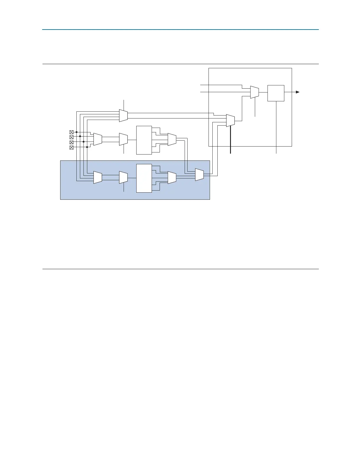
Figure 5–1 shows the clock control block.
Each PLL generates five clock outputs through the
c[4..0]
counters. Two of these
clocks can drive the GCLK through a clock control block, as shown in Figure 5–1.
f For more information about how to use the clock control block in the Quartus II
software, refer to the ALTCLKCTRL Megafunction User Guide.
Figure 5–1. Clock Control Block
Notes to Figure 5–1:
(1) The
clkswitch
signal can either be set through the configuration file or dynamically set when using the manual PLL switchover feature. The
output of the multiplexer is the input clock (f
IN
) for the PLL.
(2) The
clkselect[1..0]
signals are fed by internal logic and are used to dynamically select the clock source for the GCLK when the device is in
user mode.
(3) The static clock select signals are set in the configuration file. Therefore, dynamic control when the device is in user mode is not feasible.
(4) Two out of four PLL clock outputs are selected from adjacent PLLs to drive into the clock control block.
(5) You can use internal logic to enable or disable the GCLK in user mode.
(6)
CLK[
n
]
is not available on the left side of Cyclone IV E devices.
CLKSWITCH (1)
Static Clock Select (3)
Static Clock
Select (3)
Internal Logic
Clock Control Block
Not applicable to
Cyclone IV E devices
DPCLK
CLKSELECT[1..0] (2)
Internal Logic (5)
inclk1
inclk0
CLK[n + 3]
CLK[n + 2]
CLK[n + 1]
CLK[n] (6)
f
IN
C0
C1
C2
PLL
Global
Clock
Enable/
Disable
C3
C4
CLKSWITCH (1)
inclk1
inclk0
f
IN
C0
C1
C2
PLL
C3
C4
(4)