S820E UG PN: 10580-00343 Rev. H 8-5
Vector Voltmeter 8-2 How the VVM Function Works
A/B or B/A Measurements: For Reflection or Transmission measurements,
the S820E VVM function can replace the entire setup of source, VVM, and
couplers, as shown in Figure 8-1 and Figure 8-2. If the measurement setup
still requires the use of an external source and couplers, however, then the
S820E VVM function can replace only the original Vector Voltmeter by using
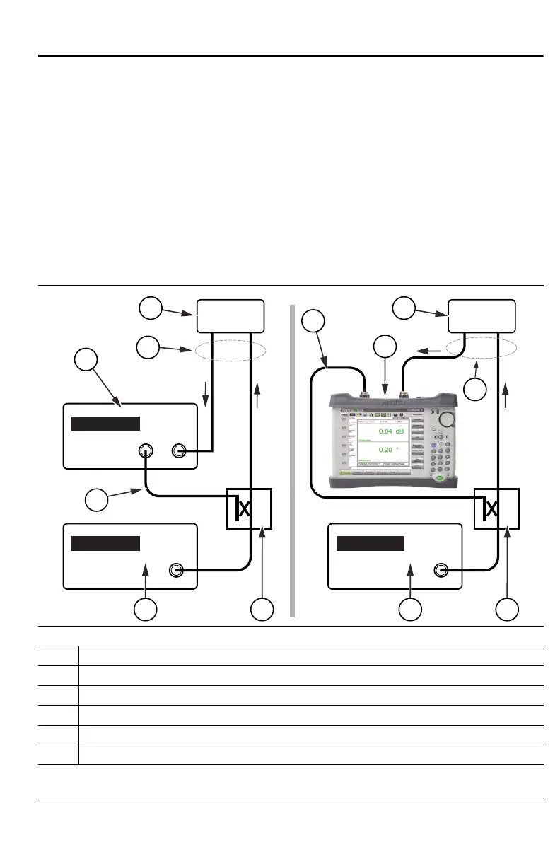
the A/B or B/A measurement selection. The B/A setup is shown in Figure 8-3
with the traditional Vector Voltmeter instrument method (left) and the
equivalent measurement using the Site Master in VVM mode (right). For
these measurements, the reference signal is received on one port of the S820E
(Port 1 for B/A and Port 2 for A/B) while the signal transmitted through or
reflected from the DUT is received on the other port.
B/A Measurement
(Left) Vector Voltmeter and (Right) S820E Site Master Equivalent Measurement
1 Vector Voltmeter or S820E Site Master
2 Coupler or Splitter
3 Signal Generator
4 Reference Signal
5 B/A Measurement
6 DUT (Device Under Test)
Figure 8-3. Vector Voltmeter B/A Measurement
2
3
5
6
1
1
2
3
5
6
4
4
DUT
Signal
Generator
DUT
Vector
Voltmeter
Signal
Generator