10. Maintenance
Concerned parts
R767261K
System-Power Board
Necessary tools
• 1 x Phillips Screw driv e r #2
• Hex Sc re w driver
How to remove the System-Power board
1. Unplug the USB, VFD, 3RU and 1RU cables that are plugged on the top side of the board and a re visible when the bottom panel
is removed. Refer to the drawing below (top side) to locate the cables.
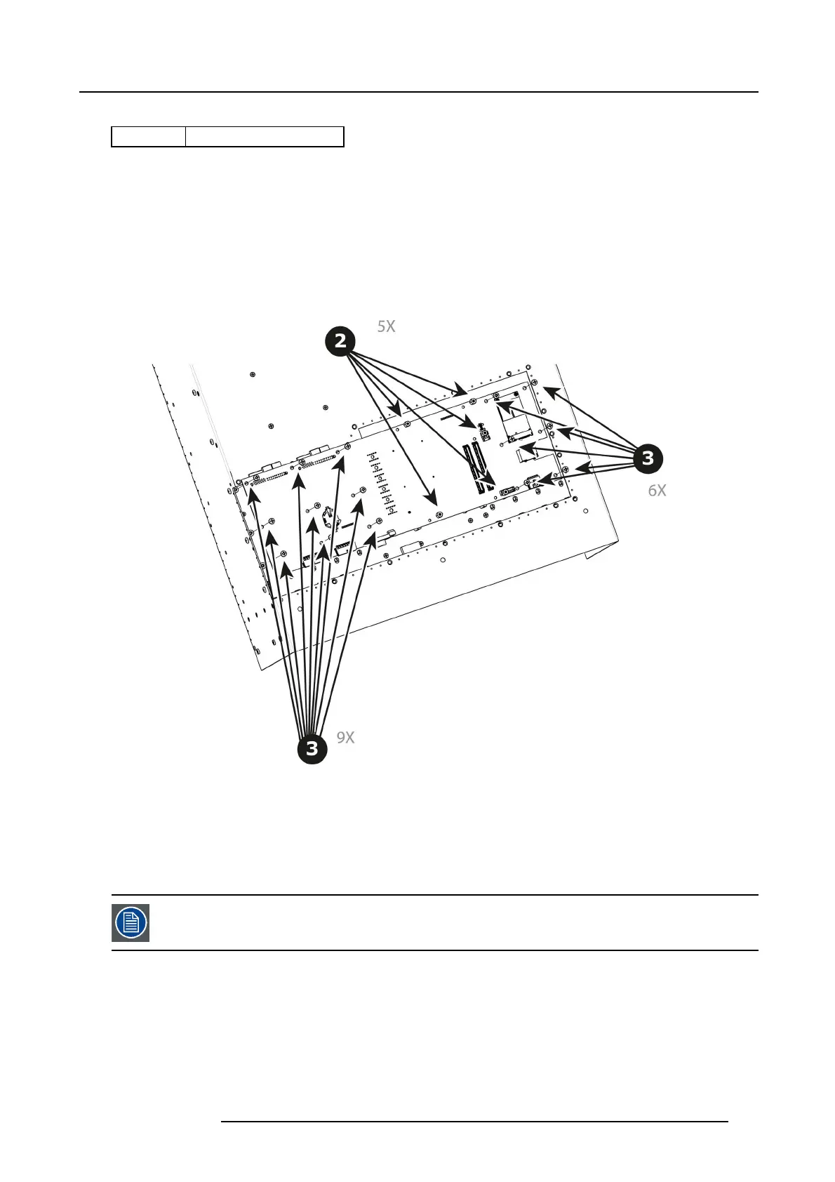
2. With the Hex Sc rewdriver, remove the 5 standoffs (m 2,5 H6 Stainless Steel) which attach the C PU module to the m otherboard.
Image 10-53
3. Remove the 15 screws (6-32x.31 Stainless Steel) that attach the System Power Board to the Mother boar d.
4. Carefully lift the board up and remove the card from the S ystem . Don’t pull the board too far because there ar e still 3 cables
attached to the card.
Note: Interposer c ard(s) may c ome out. In this case, re-install the boards into the m otherboard slots unit.
5. Turn the board over and un plug the Genlock, Ethernet cable and Front panel keyboard cable. R efer to the draw ing below ( Bottom
side) to locate the cables.
After the system card is removed, y ou can also replace the System battery or the Solid-State memory. These
items can be serviced without removing the S ystem-Pow er board as described in other sections o f this ch ap-
ter.
How to install the System-Power Board
To install the System-Power Board follow the sam e procedure in the reverse order.
R5905948 E2 12/12/2014
247