4. Hardware orientation
4.2 Rear panel
About rear panel
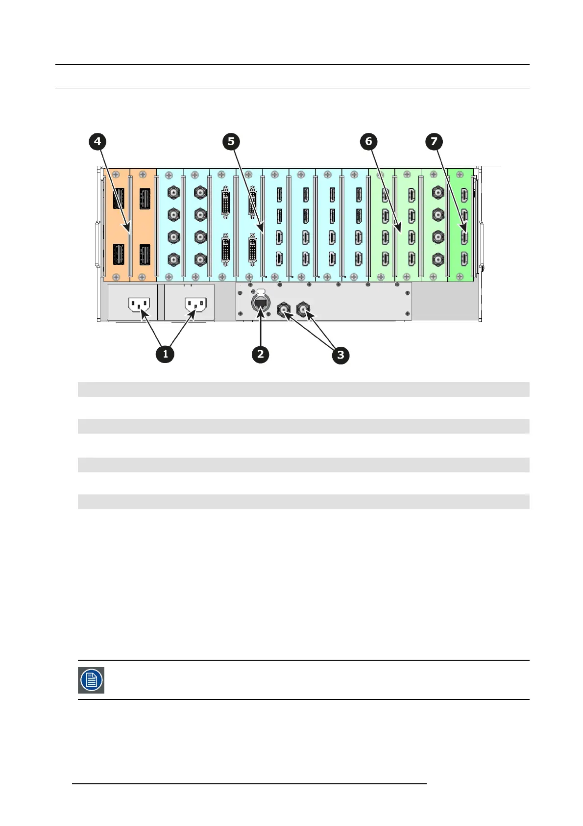
The figure below illustrates the E2 rear panel.
Image 4-4
1
Tw o AC connectors
2
RJ-45 connector for 10/100 BaseT Ethernet comm unications
3 Tw o Genloc k Input BNC with passive Loop-through
4 Tw o Expansion link cards
5
Eight Input cards (HDMI/D P, SDI, DV I)
6
Three O utputs cards (DVI, SDI)
7
One Multiviewer card (HD MI)
AC connectors
E2 is equipped with two redundant power supplies. During normal operation the load is shared equally by both supplies. If one
supply fails, the sec ond carries the whole load. Two A C Connector are provided to connect the E2 to y our facility’s A C power source
through the supplied power cords
.
Input Power Specification: 100-240 VAC, 47-63 Hz
On each power supply there a re 3 LE D lights that provide status information as follows:
• DC Output Pow er LED: when G reen, t
he supply is outputting v alid DC power.
• Status LED: when amber indicates that an error has occurred.
• AC Input P ower LED: when green it indicates that the supply is connected to a valid AC power.
Therefore, during normal operating conditions, the input AC and O utput DC LEDs will turn green.
Note that the power supplies are installed upside down, so the silkscreen markings will also appear upside
dow n.
Ethernet port
One RJ-45 connector is provided for 10/100Bas eT E thernet c omm unications with the E2. The port is used for running the Web
Interface an d for connection to an external device.
32
R5905948 E2 12/12/2014