10. Maintenance
10.29 Ethernet Cable
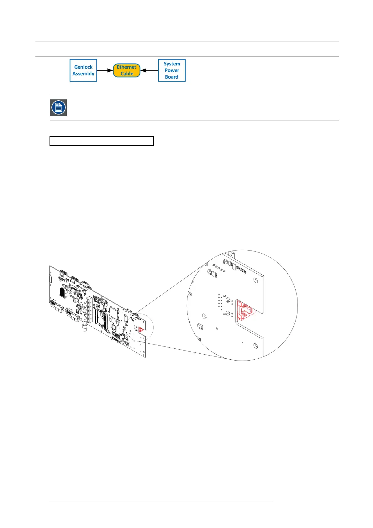
Image 10-74
The Ethernet cable connects the Genlock board to the System Power board. This procedure provides instruc-
tions on how to remove the cable from both sides.
Concerned parts
R767269K
Cable K it S et
Necessary tools
1 x Phillips Screwdriver #2
How to remove the Ethernet cable
1. Follow the steps detailed in other procedures to remove Ethernet cable from the Genlock assembly.
2. Turn the unit upside down and follow the s teps detailed in other procedures to remove the B ottom P anel and the CPU m odule
from the System-Power board.
3. Remove the USB, VFD, 3RU and 1RU cables that are connected to the System-Power board.
4. Remove the screws that attach the System-Power Board to the standoffs.
5. Lift the System Power B oard from the standoffs and flip it ove r, but don’t extend it too m uch.
6. Locate the E thernet con nector and push the locking clip on the Ethernet cable so it can be released from the socket.
Image 10-75
7. Carefully remove the cable from the unit.
How to install the Ethernet Cable
To install the Ethernet Cable follow the same procedure in the reverse o rder.
264
R5905948 E2 12/12/2014