2-12 Starling Monitor - User Guide
System Configuration
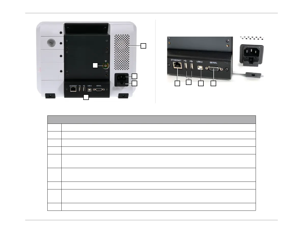
Figure 2-7 Starling Monitor - Rear View
Legend, Figure 2-7
1
AC Power input socket.
2
Fuse housing.
3
Connectors panel.
4
Ground connector.
5
Ethernet connector - used to connect the Monitor to an external third-party system
(e.g. Patient Monitor or EMR system).
6
USB ports - enables user to connect a USB Thumb Drive (USB storage device)
to Export acquired monitoring results stored in the Starling Monitor database.
7
USB-2 port - for use by Service personnel only.
8
Serial port - used to connect the Monitor to an external third-party system
(e.g. Patient Monitor or EMR system).
9
Air inlet ventilation port.