InteliDrive DCU Marine - 3.0.0 Global Guide
260
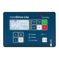
How to indicate AIN8 protection on BO?
1. Select free universal state for selected protection
Note: Configure this UnivState to some Binary output and modify Bin output Name.
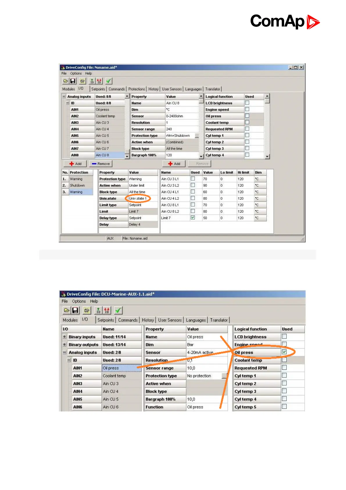
Oil pressure and Water temperature on the first ID controller screen indication
1. Reading from ID-DCU MARINE analog inputs