InteliDrive DCU Marine - 3.0.0 Global Guide
43
RPM Secondary RPM
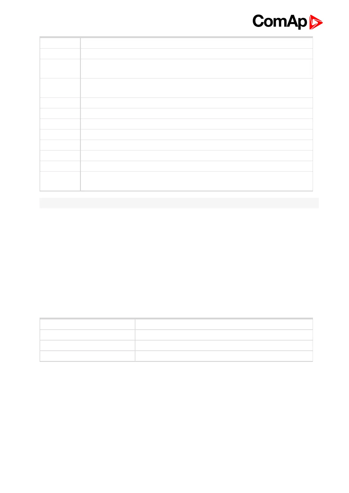
+SOL Common power supply for galvanic separated Fuel solenoid and Stop solenoid outputs.
FUEL SOL
Fuel solenoid output, High side switch (8 Amps), BW detection in open state or above 1
amp load
STOP SOL
Stop solenoid output, High side switch (8 Amps), BW detection in open state or above 1
amp load
GND SOL Common GND for Fuel and Stop solenoid outputs
COMM.SD Common Shut down output, Low side switch (0,5 Amps)
COMM.WRN Common Warning output, Low side switch (0,5 Amps)
SD1 to SD5 Shut down inputs, BW detection, Normally open
EM.STOP Emergency stop input, Normally closed
A+, A- Primary battery
B+, B- Secondary battery
COM+,
COM-
Battery A, B output to ID-DCU MARINE
Note: 10 kΩ resistor must be connected in parallel to SD1 to SD5 inputs.
4.1.9 ID-SCM Speed control module
ID-SCM module is interface module for InteliDrive controller application. Module is mounted directly to ID-DCU
MARINE controller case. Module power supply: 8 to 36VDC.
Inputs
RPM1, RPM2: Two inputs for frequency (e.g. flow) measuring. Expected sensor is magnetic pickup – with
maximal frequency range up to 8 kHz. The output values SCM Freq1, SCM Freq2 calculation use setpoints
SCM unit: FreqRate1 and FreqRate2 - see below.
Closed jumper divides input frequency by 16 - recommended for higher frequency (>1000Hz) measuring.
Jumper position does not influence output value range.
Jumper RPM input nominal frequency range
Closed > 1000 Hz
Closed or Opened 500 - 1000 Hz
Opened 500 Hz
IMP1, IMP2: Two impulse inputs for integral (e.g. consumption) measuring. It is expected NPN – open collector
(active) impulse sensor with maximal frequency range up to 60 Hz. Minimal pulse duration is 1ms. The output
values SCM Imp1, SCM Imp2 calculation use setpoints SCM unit: TransferRate1 and TransferRate2 - see
below.
ID-SCM inputs wiring example