InteliDrive DCU Marine - 3.0.0 Global Guide
77
0 to 20 mA
0 to 10 VDC
PWM (Pulse With Modulation on 1,2 kHz)
I-AOUT8 modules is connected on CAN 1 (peripheral) bus. The corresponding module Address 1 to 4 (default 1)
must be set on module (by Adr.1 and Adr.2 jumpers) and in controller configuration. Communication fail is
indicated in controller Alarm list and by binary output. Use GenConfig PC tool for controller configuration.
It is possible to connect up to four I-AOUT8 units to one controller.
I-AOUT8 unit can be mounted on DIN rail (35 mm).
CAN 1 terminating 120 Ω resistor jumper is connected in default. AGND terminals are on the same potential.
Number of analog outputs 8, no galvanic separation
Type of analog outputs (jumper selectable) U 0 to 10VDC ± 1% , max 5 mA
I 0 to 20 mA ± 1% , max 500 Ω
p pwm 1200 Hz, 5V level, max 10 mA
Power supply 8 to 36 VDC
Current consumption 100 ÷ 300 mA at 24 VDC
Communication interface CAN1, with jumper selectable address 1 to 4 Jumper selectable terminating resistor 120 Ω
RS232 interface TTL, firmware upgrade via AT-link.
Operating temperature range - 40°C to +70°C
Analog outputs refreshment Max. 300 ms
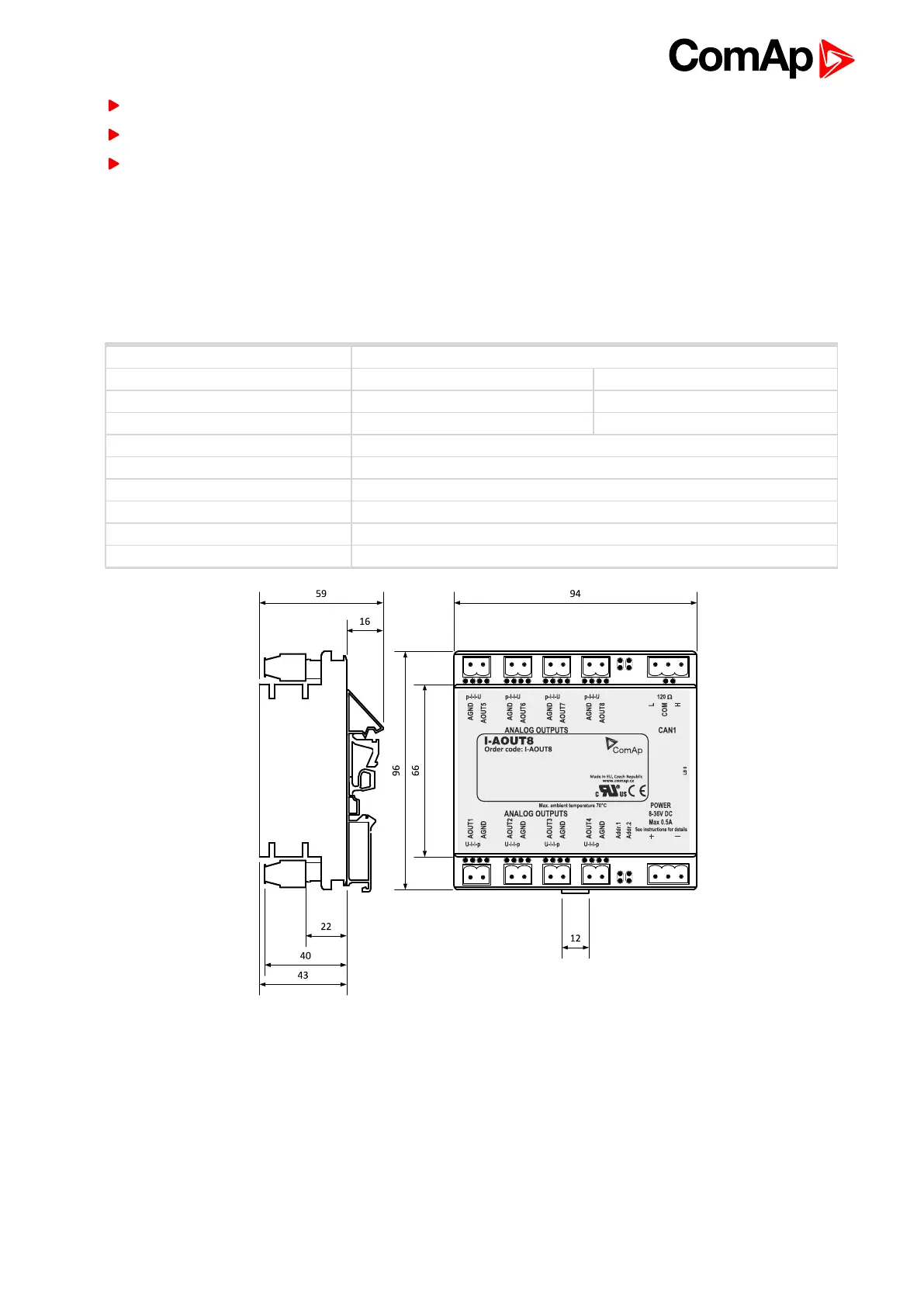
Image 4.15 Dimensions of I-AOUT8
All dimensions are in mm.
I-AOUT8 unit can be mounted on DIN rail (35 mm).
Connection of Multiple Units
Up to four modules can be connected to one controller. Set module CAN address corresponding to configuration
according table below.