EasyManuals Logo

ComAp InteliDrive DCU Marine User Manual

ComAp InteliDrive DCU Marine
285 pages
To Next Page IconTo Next Page
To Previous Page IconTo Previous Page
Page #41 background imageLoading...
Page #41 background image
InteliDrive DCU Marine - 3.0.0 Global Guide
41
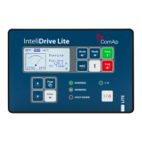
Note: Put jumper to connect the internal 120 Ω terminating resistor for CAN2 interface. ID-COM module is not
required when inter-controller CAN2 line is not used. In this case connect Extension modules CAN1 directly to
Extension modules port ID-COM on ID-DCU MARINE (9-pin connector: 5=H, 9=L).
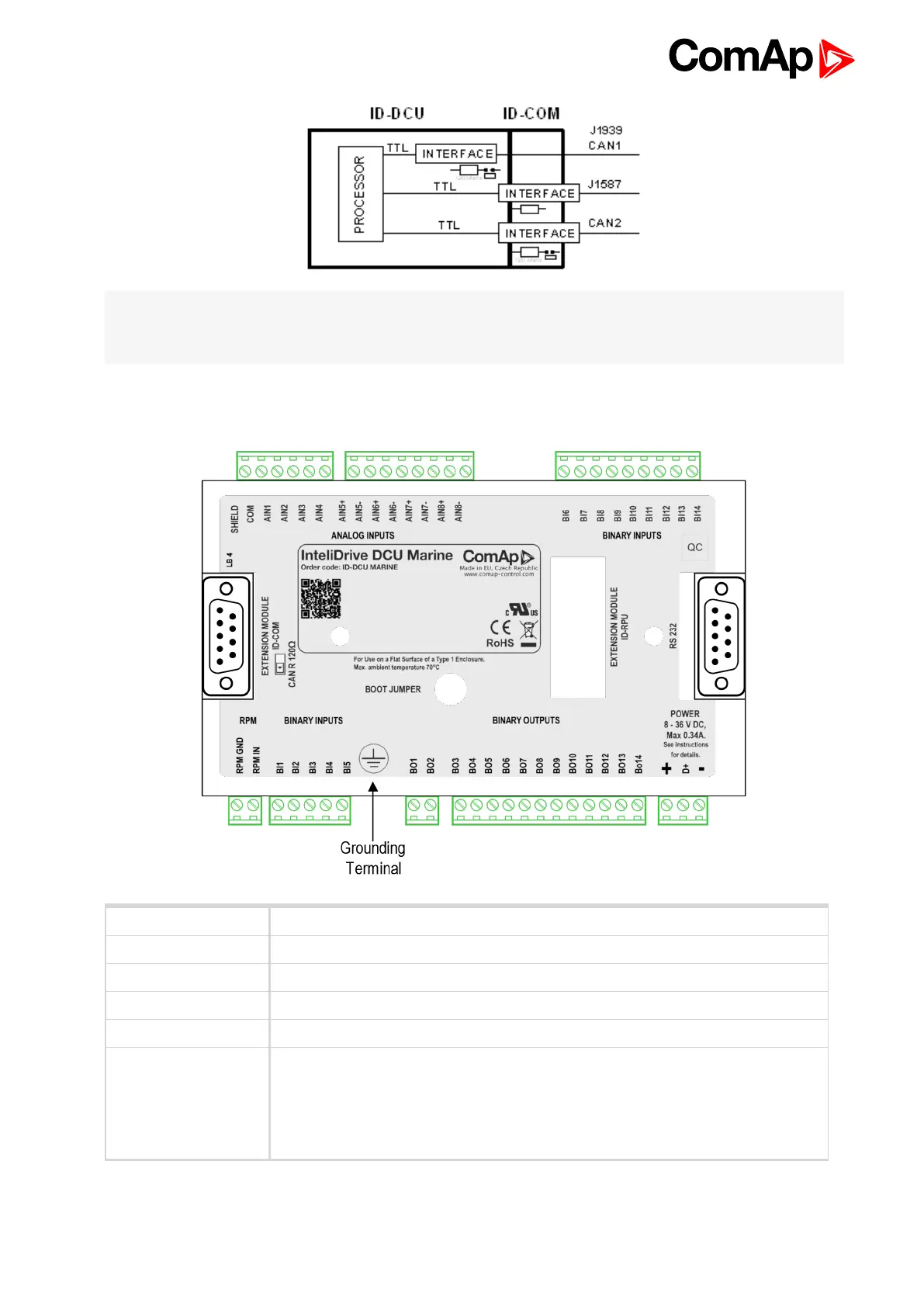
4.1.6 ID-DCU MARINE terminals
RPM Primary RPM
BI1 to BI14 Binary inputs, active when closed to minus power supply
BO1 to BO14 Binary outputs; Low side switch; 0,5 Amps each;
D+ D plus terminal
AIN1 to AIN4 Analog inputs - group 1
AIN5+, AIN5-
AIN6+, AIN6-
AIN7+, AIN7-
AIN8+, AIN8-
Analog inputs - group 2

Table of Contents

Other manuals for ComAp InteliDrive DCU Marine

Questions and Answers:

Question and Answer IconNeed help?

Do you have a question about the ComAp InteliDrive DCU Marine and is the answer not in the manual?

ComAp InteliDrive DCU Marine Specifications

General IconGeneral
BrandComAp
ModelInteliDrive DCU Marine
CategoryController
LanguageEnglish

Related product manuals