InteliDrive DCU Marine - 3.0.0 Global Guide
34
Power supply terminals A+, A-, B+, B-, COM+, COM-
The ID-RPU module has two independent power input terminals and one power output terminals. The power
output is supplied from battery A and if this voltage drops under 8V, the relay switches to the power supply B.
Battery B is switched to A when: Batt A > 10VDC and Fault reset button is pressed on ID-DCU MARINE or
Batt reset button is pressed on ID-RPU when ID-DCU MARINE is out of order. The voltage switching levels is
fix set in the ID-RPU.
Note: Short supply drop out occurs during battery A to B or B to A switching. Connect B terminals in parallel to
A when redundant battery B is not used.
Binary inputs SD1 .. SD5 – shutdown channels
Include broken wire detection. The input logic is Normally Opened. Inputs are NOT active if controller unit is in
EME mode or Sd override is active. No LED indication.
Note: There is no I/O state or Broken wire LED indication on ID-RPU module. All indications are visible on ID-
DCU MARINE screen include Alarm list and History record.
Binary input Emergency stop
No Broken wire detection. The input logic is Normally Closed. Input is active in all EME, AUX and PRP modes.
No LED indication.
Binary output COMMSD
Output indicates any shutdown Alarm.
Normal mode: the output is controlled from ID-DCU MARINE (Binary output Comm Sd)
Backup mode: the output is activated if RPU emergency stop or SD1 – SD5 become active.
Binary output COMMWRN
Common warning indication.
Normal mode: the output is controlled from ID-DCU MARINE (Binary output Comm Wrn)
Backup mode: the output is ACTIVE.
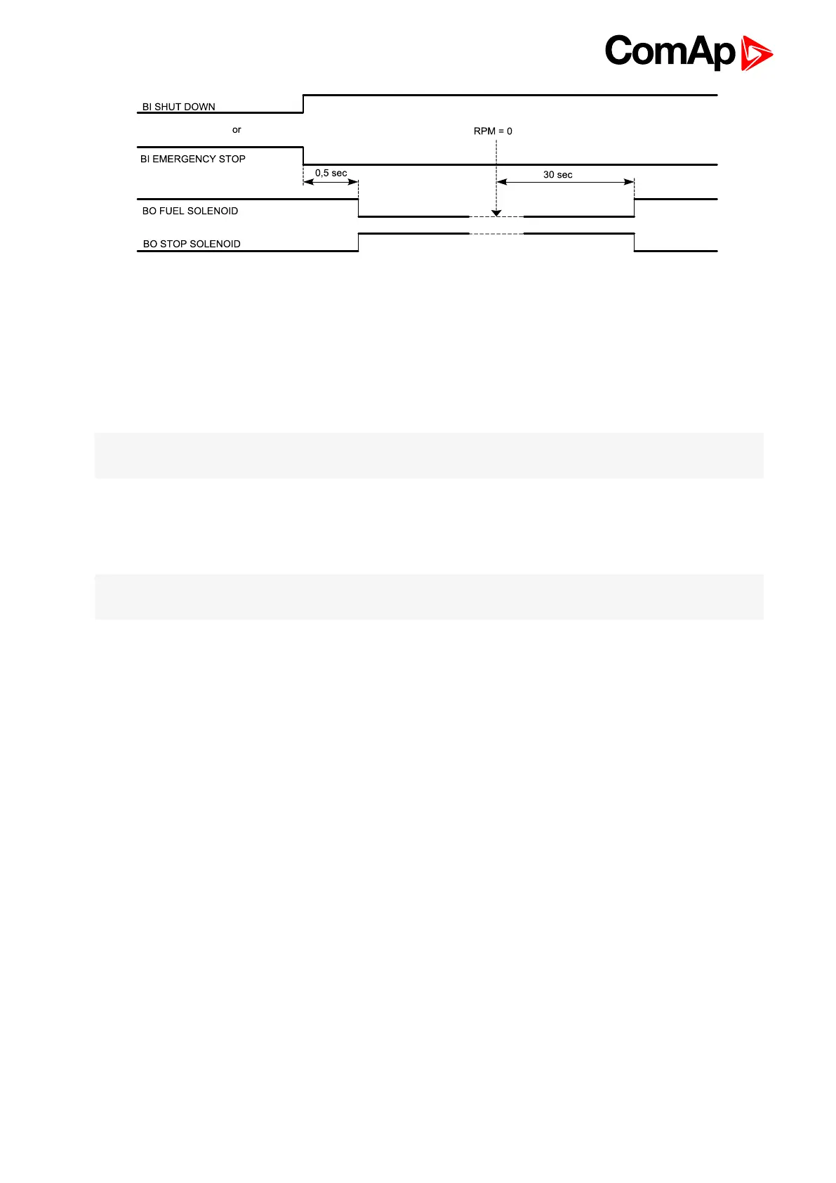
Binary output STOP SOL
Stop solenoid output (high side switch) with broken wire (BW) detection active on opened output.
Normal mode: the output is controlled from the ID-DCU MARINE. The logical output Stop solenoid must be
configured to this output in the configuration of ID-DCU MARINE. In case the stop solenoid is not used, the
output must be configured as not used, otherwise broken wire protection will be detected.