InteliDrive DCU Marine - 3.0.0 Global Guide
78
CAN Address Jumper 1 Jumper 2
1 No No
2 Yes No
3 No Yes
4 Yes Yes
Analog outputs Modification (U, I, PWM)
Follow the p-I-I-U symbols on the module sticker. There are two equivalent positions for mA measuring.
AOUT jumper Symbol Function
p PWM
Pulse - Widht - Modulation
I 0 to 20 mA
U 0 to 10 VDC
LED Indication
Green LEDis located near the power supply connector.
I-AOUT8 module state LED Pwr
No power supply Dark
Memory fail Fast blink (100/100 ms)
Communication fail Slow blink (300/300 ms)
Communication fail Continuous light
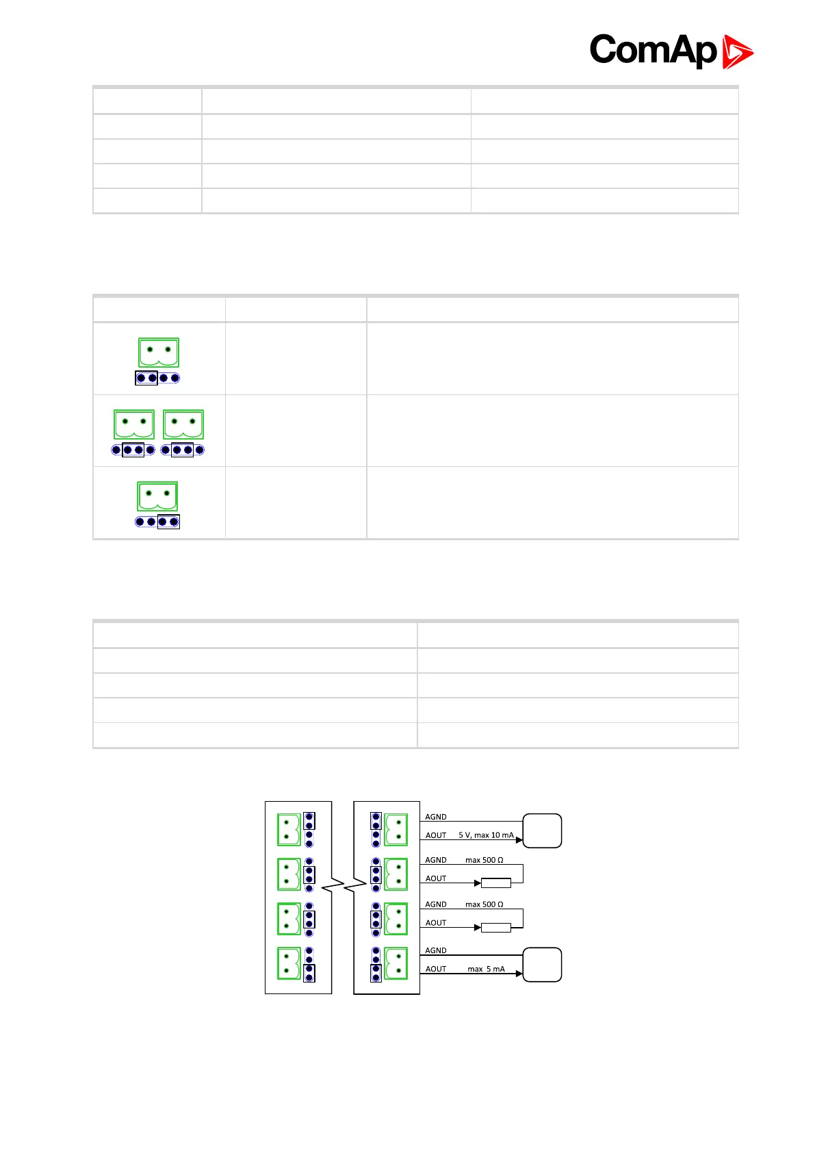
Wiring and jumer setting example
Voltage output 0 to 10 VDC Pwm output 1200 Hz
Current output 0 to 20 mA Current output 0 to 20 mA
Current output 0 to 20 mA Current output 0 to 20 mA
Pwm output Voltage output 0 to 10 VDC
6 back to Installation and wiring