Ê Lower the system board carefully into the chassis.
Ê Adjust the system board. If necessary adjust the position of the system
board with a gentle twisting motion (orange circles in figure 241 on page 331
show the centering bolts).
Ê Fasten the system board with the 14 screws (see figure 241 on page 331).
Ê Remove the processor from the defective system board as described in
section "Removing the defective processor" on page 253.
Ê Remove the protective plastic cover from the processor socket of the new
system board and fit it onto the socket of the defective system board which
will be sent back to spares.
I Returned system boards without this cover probably have to be
scrapped.
Ê Install the processor on the new system board as described in section
"Installing the new processor" on page 256.
Ê Reconnect all cables to the system board:
– Front panel cable
– Front USB cable
– Power cable for HDD backplane
– SATA cable(s) for HDD backplane
– SATA cable for ODD (if applicable)
– Power cable for ODD (if applicable)
– Front VGA cable (if applicable)
– OOB cable (if applicable)
For the cable plan see section "Cabling" on page 339.
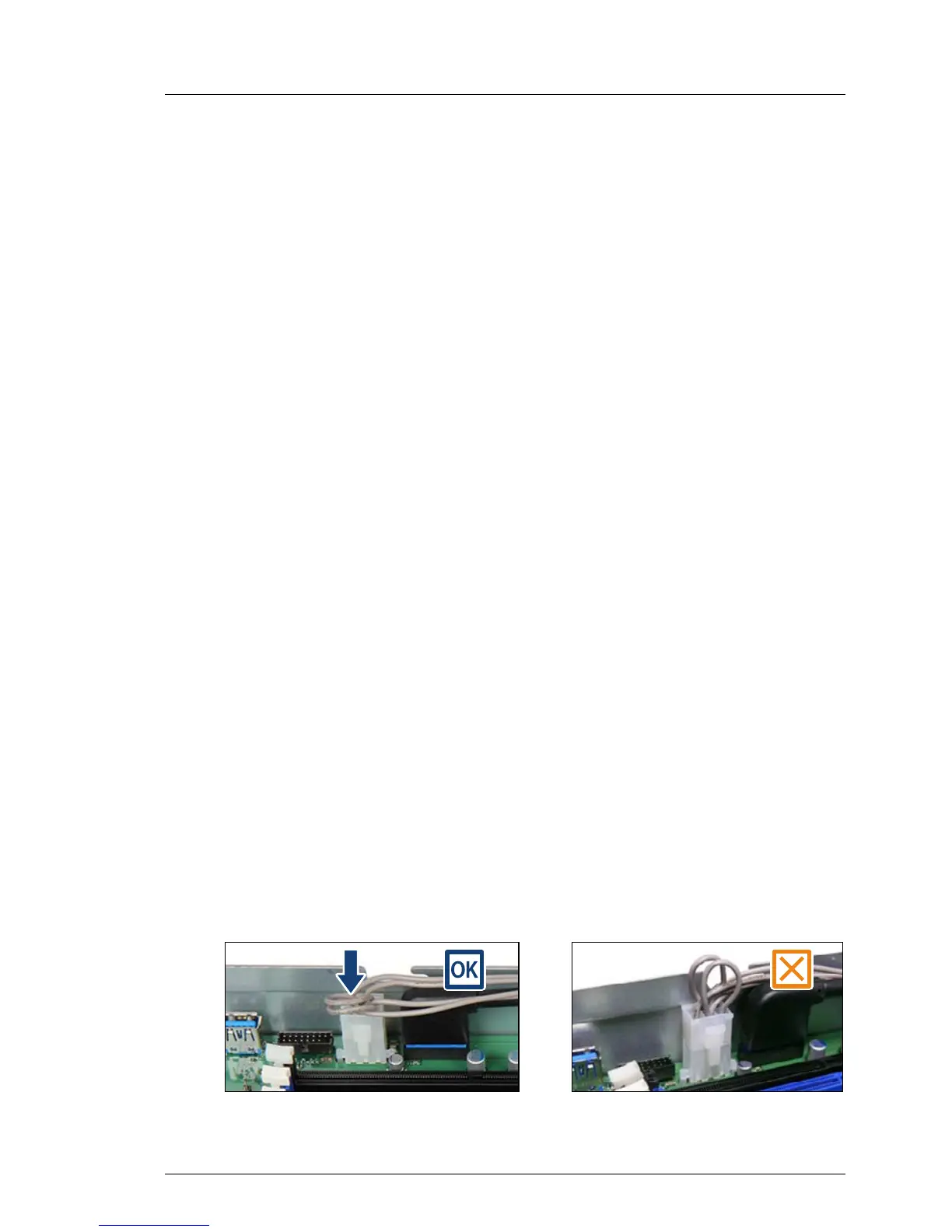
V CAUTION!
Ê Press down the loops of the power cable for HDD backplane to
ensure that the power cable is completely inside the chassis.

 Loading...