EasyManua.ls Logo

Fujitsu PRIMERGY RX2530 M1

Fujitsu PRIMERGY RX2530 M1
372 pages
To Next Page IconTo Next Page
To Previous Page IconTo Previous Page
Loading...
360 Upgrade and Maintenance Manual
RX2530 M1
Appendix
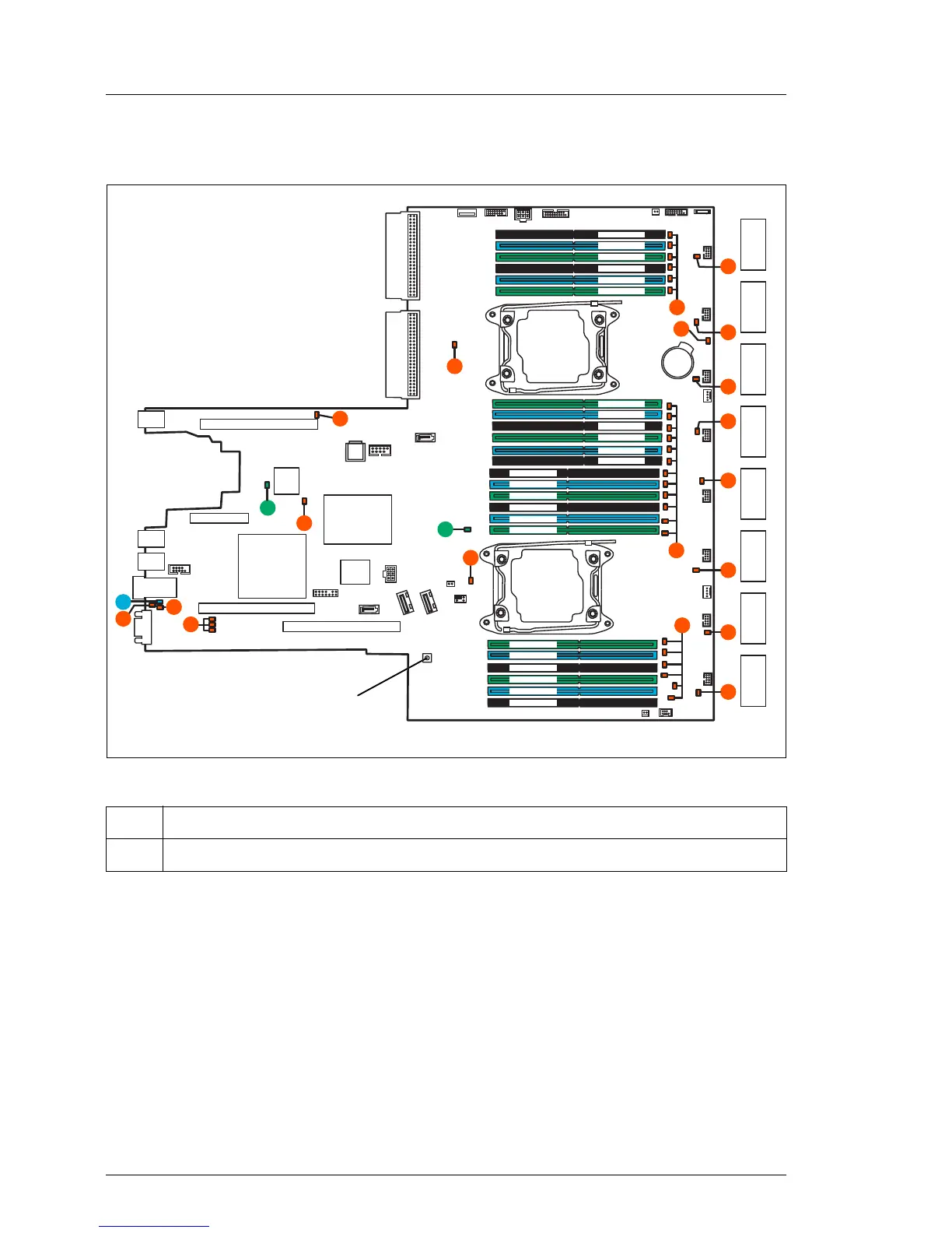
17.2.1.2 Onboard indicators and controls
Figure 265: Onboard indicators and Indicate CSS button
I LEDs A, B and C are visible from outside on the server rear. All other
LEDs are only visible if the server cover has been opened.
If the server has been powered off (power plugs must be disconnected) it is
possible to indicate the faulty component by pressing the indicate CSS button.
Pos. Description
1 Indicate CSS button
iRMC
S4
external connectors
INDICATE
CSS
TPM
I
Battery
VGA
USB 2
USB 3
Management
LAN
Slot riser card / slot 1 and 2
PCH
CPU 1 DIMM 3D
L
JP3
FAN 11/
12 SYS
SATA
1-4
Front
Panel
Front
VGA
G
FAN 9/
10 SYS
FAN 7/8
SYS
FAN 5/6
SYS
FAN 3/4
SYS
FAN 1/2
SYS
USB 1
Slot riser card / slot 3
Slot riser card / slot 4
Slot 3
K
K
FAN
11/12
FAN
9/10
FAN
7/8
FAN
5/6
FAN
3/4
FAN
1/2
UFM
SERIAL 1
B
C
A
H
FAN
13/14
FAN
15/16
G
K
K
K
CPU 1
CPU 2
Slot 2
Slot 1
F
Slot 4
F
H
CPU 1 DIMM 2D
CPU 1 DIMM 1D
CPU 1 DIMM 3C
CPU 1 DIMM 2C
CPU 1 DIMM 1C
CPU 2 DIMM 3H
CPU 2 DIMM 2H
CPU 2 DIMM 1H
CPU 2 DIMM 3G
CPU 2 DIMM 2G
CPU 2 DIMM 1G
CPU 1 DIMM 1A
CPU 1 DIMM 2A
CPU 1 DIMM 3A
CPU 1 DIMM 1B
CPU 1 DIMM 2B
CPU 1 DIMM 3B
CPU 2 DIMM 1E
CPU 2 DIMM 2E
CPU 2 DIMM 3E
CPU 2 DIMM 1F
CPU 2 DIMM 2F
CPU 2 DIMM 3F
K
K
FAN 13/
14 SYS
FAN 15/16
SYS
PWR4
SMB4
FAN17
FAN18
K
H
Front
Panel
PWR2
PWR1
Front USB3.0
PWR3
Micro
SD
SATA
7-10
SATA 6
DOM
SATA 5
Internal
USB3.0
PSU1
PSU2
JP2
JP1
1
1
2
Slot LoM modules
M
N

Table of Contents

Other manuals for Fujitsu PRIMERGY RX2530 M1

Related product manuals