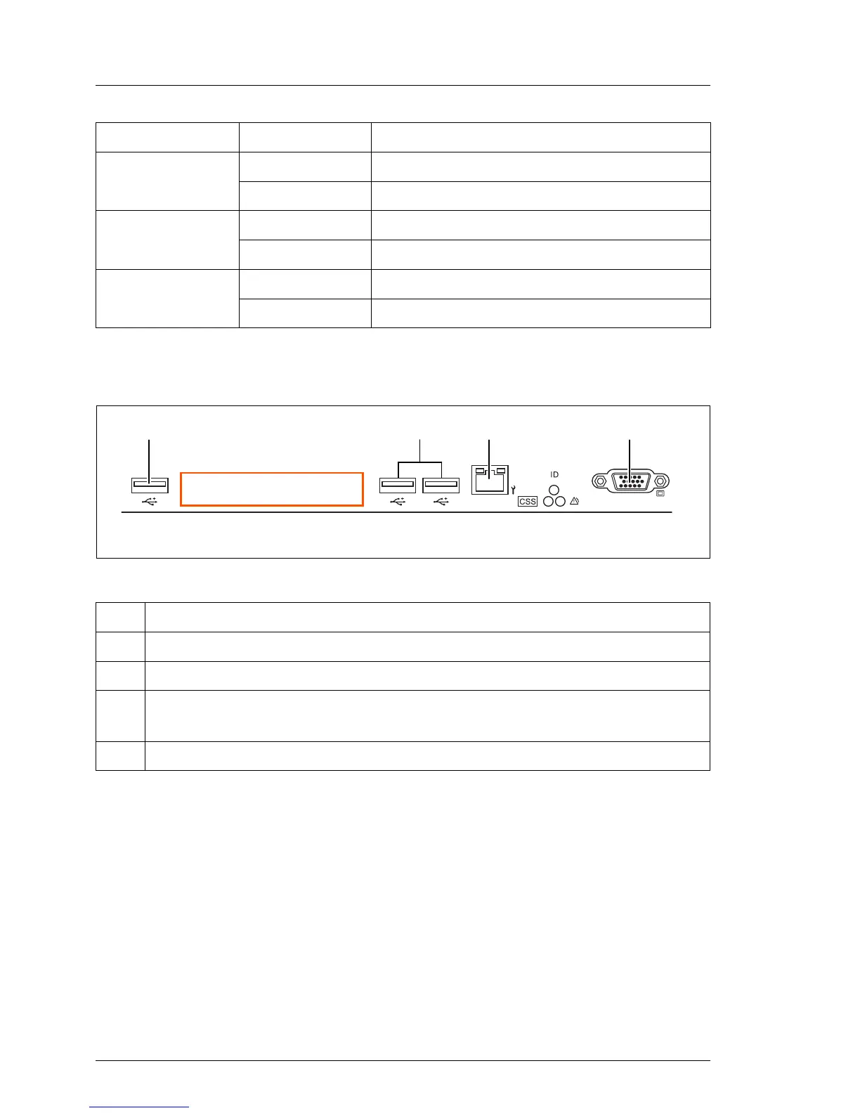
17.2.1.3 I/O panel connectors
Figure 266: Connector panel
Note for LAN connectors on dynamic LoM modules
The LAN connectors on the dynamic LoM modules are numbered in ascending
order from right to left beginning with “0”. The rightmost connector (LAN 0) is the
shared LAN connector respectively.
Depending on BIOS settings, the shared LAN connector may also be used as
a management LAN connector. For further information, please refer to the
corresponding BIOS Setup Utility reference manual.
L - Battery off
orange on Battery failure
M - Standby
Power
off
orange on All standby voltages ok
N - Main Power off
green on All main voltages ok
Pos. Description
1 1x USB 2.0 connectors
2 2x USB 3.0 connectors
3 Management LAN connector (for iRMC S4 server management
function)
4 Video connector (VGA)
LED Indicator Meaning

 Loading...