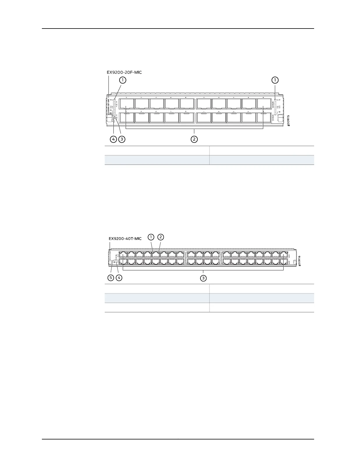
Figure 29: EX9200-20F-MIC
3—1— MIC LEDLEDs for the ports
4—2— MIC power button1-Gigabit Ethernet ports
•
EX9200-40T-MIC, which has 40 RJ-45 ports, which can accept RJ-45 connectors.
The ports are divided into three port groups. The ports labeled 0/1 through 1/5 and
0/0 through 1/4 form port group pic0, the ports labeled 1/7 through 2/3 and 1/6
through 2/2 form port group pic1, and the ports labeled 2/5 through 3/9 and 2/4
through 3/8 form port group pic2. An LED labeled OK/FAIL on the MIC indicates the
status of the MIC. See “Modular InterfaceCardLED in an EX9200 Switch” on page 34.
See Figure 30 on page 61.
Figure 30: EX9200-40T-MIC
4—1— MIC power buttonLink/Activity LED for the ports
5—2— MIC LEDStatus LED the ports
3—RJ-45 ports
•
Cover panels—Two cover panels that cover the MIC slots.
•
Line card LED—An LED labeled OK/FAIL, which indicates the status of the line card.
See “Line Card LED in an EX9200 Switch” on page 71.
•
Network port LEDs—Each port on the EX9200-10XS-MIC and each port on the
EX9200-20F-MIC has an LED, the Link/Activity LED, which indicates the link status
and activity on the port. Each port on the EX9200-40T-MIC has another LED, the Status
LED, which indicates the status of the port parameters. See “Network Port LEDs on
Line Cards in an EX9200 Switch” on page 33.
Related
Documentation
Line Card Model and Version Compatibility in an EX9200 Switch on page 51•
• Pluggable Transceivers Supported on EX9200 Switches on page 103
61Copyright © 2017, Juniper Networks, Inc.
Chapter 5: Line Cards