Gocator 2300 & 2880 Series
Gocator Web Interface • Output • 209
Output
The following sections describe the Output page.
Output Page Overview
Output configuration tasks are performed using the Output page. Gocator sensors can transmit laser
profiles and measurement results to various external devices using several output interface options.
Up to two outputs can have scheduling enabled with ASCII as the Serial output protocol. When
Selcom is the current Serial output protocol, only one other output can have scheduling
enabled.
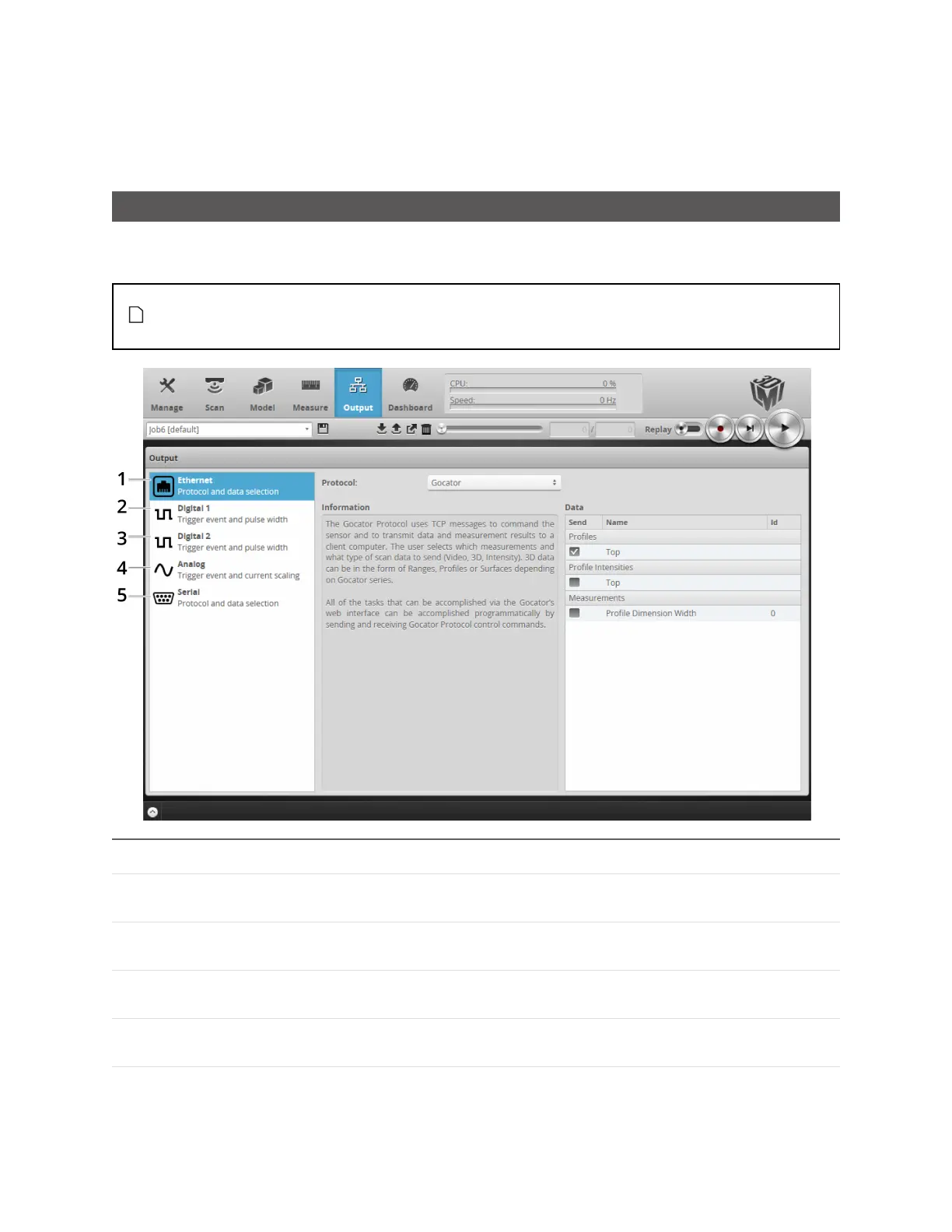
Category Description
1 Ethernet Used to select the data sources that will transmit data via Ethernet. See
Ethernet Output on the next page.
2 Digital Output 1 Used to select the data sources that will be combined to produce a digital
output pulse on Output 1. See Digital Output on page 213.
3 Digital Output 2 Used to select the data sources that will be combined to produce a digital
output pulse on Output 2. See Digital Output on page 213.
4 Analog Panel Used to convert a measurement value or decision into an analog output
signal. See Analog Output on page 216.
5 Serial Panel Used to select the measurements that will be transmitted via RS-485
serial output. See Serial Output on page 218.
 Loading...

