Gocator 2300 & 2880 Series
Specifications • Gocator 2300 &2880 I/O Connector • 410
Function Pins
Max Collector
Current
Max Collector–Emitter
Voltage
Min Pulse Width
Out_1 N, O 40 mA 70 V 20 us
Out_2 S, T 40 mA 70 V 20 us
The resistors shown above are calculated by R = (V+) / 2.5 mA.
The size of the resistors is determined by power = (V+)^2 / R.
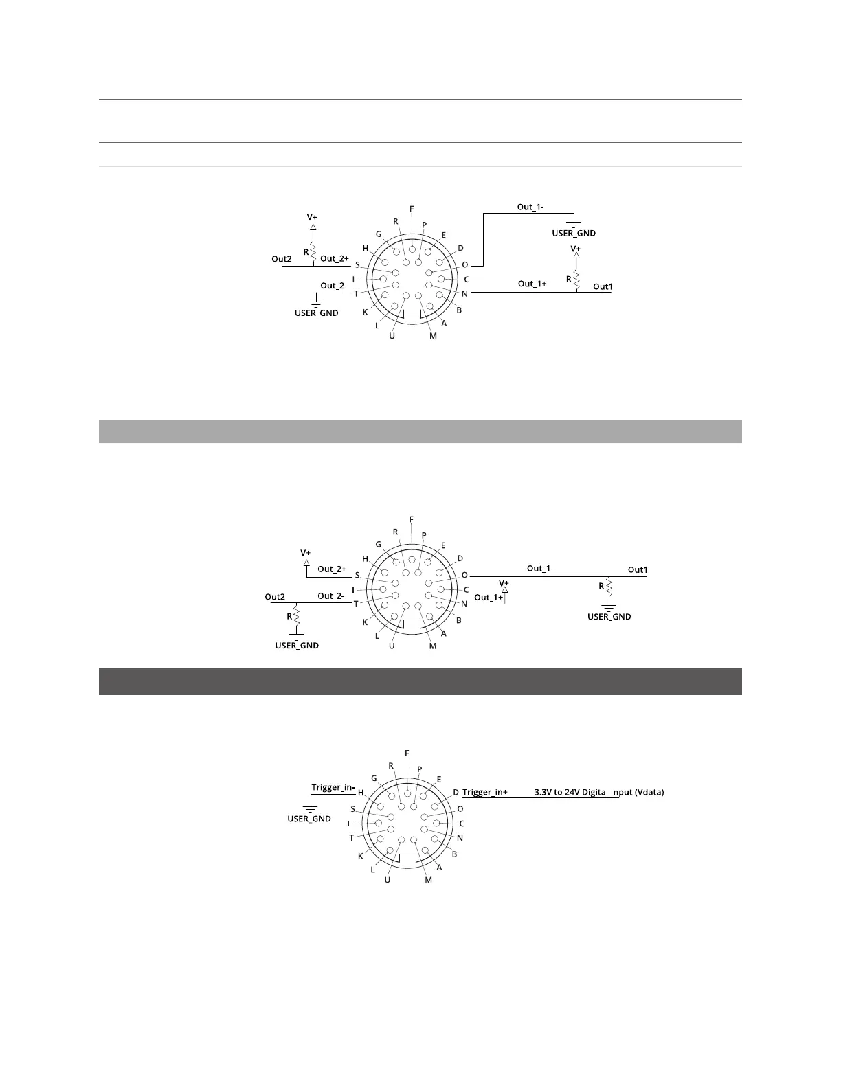
Inverting Outputs
To invert an output, connect a resistor between ground and Out_1- or Out_2- and connect Out_1+ or
Out_2+ to the supply voltage. Take the output at Out_1- or Out_2-. The resistor selection is the same as
what is shown above.
Digital Inputs
Every Gocator sensor has a single optically isolated input. To use this input without an external resistor,
supply 3.3 - 24 V to Pin D and GND to Pin H.
Active High
If the supplied voltage is greater than 24 V, connect an external resistor in series to Pin D. The resistor
value should be R = [(Vin-1.2V)/10mA]-680.

 Loading...