Gocator 2300 & 2880 Series
Gocator Web Interface • Scan Setup and Alignment • 74
Element Description
8 Data Viewer Displays sensor data and adjusts regions of interest. Depending on the current operation
mode, the data viewer can display video images , profile plots, or surface views . See Data
Viewer on page 107.
The following table provides quick references for specific goals that you can achieve from the panels in
the Scan page.
Goal Reference
Select a trigger source that is appropriate for the application.
Triggers (page 75)
Ensure that camera exposure is appropriate for laser profiling .
Exposure (page 84)
Find the right balance between profile quality, speed, and CPU utilization. Active Area (page 80)
Exposure (page 84)
Job Files (page 236)
Specify mounting orientations for dual-sensor systems.
Dual-Sensor System Layout (page
58)
Calibrate the system so that laser profile data can be aligned to a common
reference and values can be correctly scaled in the axis of motion.
Aligning Sensors (page 94)
Set up the part detection logic to create discrete objects from surfaces or profiles.
Part Detection (page 103)
Specify smoothing, gap-filling, and resampling parameters to remove effects of
occlusions.
Filters (page 97)
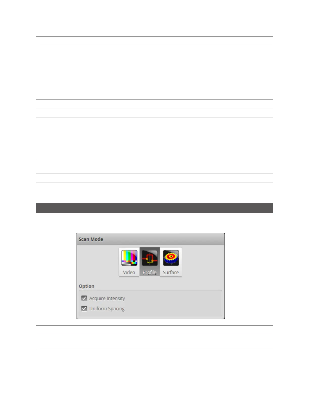
Scan Modes
The Gocator web interface supports threescan modes: Video, Profile, and Surface. The scan mode can be
selected in the Scan Mode panel.
Mode and Option Description
Video Outputs video images from the Gocator. This mode is useful for configuring exposure
time and troubleshooting stray light or ambient light problems.
Profile
Outputs profiles and performs profile measurements.

 Loading...