Operating elements for crane operation
8.2 Brief description of the operating elements
Operating Instructions GMK5250L 3 302 633 en 8 - 133
27.09.2017
Accept the measured outrigger span
Select and confirm – the outrigger span provided by the outrigger width
monitoring is adopted and shown on the
Enter outrigger span display;
à Confirm the rigging mode and lifting capacity table, p. 10 - 41.
Enter outrigger span
(
MAXbase)
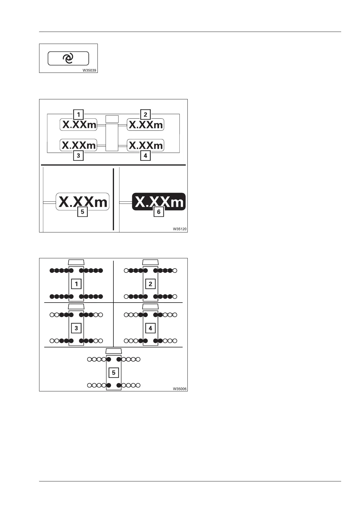
The values are entered individually for
outrigger beams (1) to (4).
In input mode – select and confirm the
individual widths.
Outrigger span monitoring display
(
MAXbase)
à Enter rigging mode, p. 10 - 32
Enter outrigger span
(
Standard)
The selection occurs simultaneously for all
outrigger beams – selected outrigger widths
are orange.
In input mode – select and confirm the
outrigger span
For the special outrigger span of 5.287 m x
7.800 / 2.500 m (17.3 ft x 25.6 / 8.2 ft) the sym-
bol (1) is displayed after entering the RCL
code.
à Enter rigging mode, p. 10 - 32
s
5 Measured outrigger width = required
width
6 Measured outrigger width ≠ of required
width
1 8.950 x 7.800 m (29.4 x 25.6 ft)
2 8.950 x 6.854 m (29.4 x 22.4 ft)
3 8.950 x 5.910 m (29.4 x 19.4 ft)
4 8.950 x 4.310 m (29.4 x 14.2 ft)
5 8.950 x 2.710 m (29.4 x 8.8 ft)

 Loading...