Rigging work
11.9 Rigging/unrigging the counterweight
Operating Instructions GMK5250L 3 302 633 en 11 - 77
27.09.2017
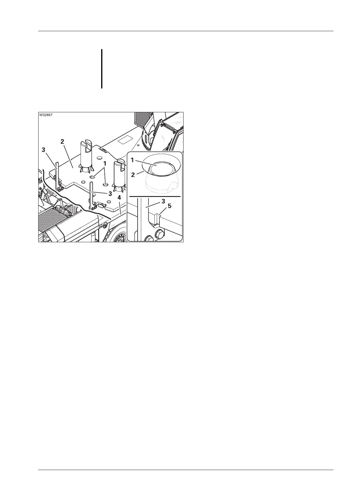
Set down 7 t (15,432 lbs) base plate
The linkage (3) is not provided as a guide for
the counterweight. The linkage serves only as
protection for parts that are located behind the
driver's cab.
• Place the 7 t base plate (2) so that it fits into
the guides (1).
Between the cutouts (5) and the linkage (3)
there is a distance of approx. 30 mm (1.2 in).
You can use the side (4) of the counterweight
platform as a guide for orientation when
setting the base plate down in the lateral
direction.
For longitudinal orientation we recommend
noting the current working radius on a base
plate that has been set down correctly.
For larger counterweight combinations, now set additional counterweight
sections onto the 7 t base plate.
s
G
Risk of accidents due to falling counterweight sections!
Only attach the counterweight sections to the appropriate slinging points
and use lifting gear of sufficient load bearing capacity.
The counterweight sections should be lifted only one at a time. The slinging
points are not designed for hoisting stacked counterweight sections.

 Loading...