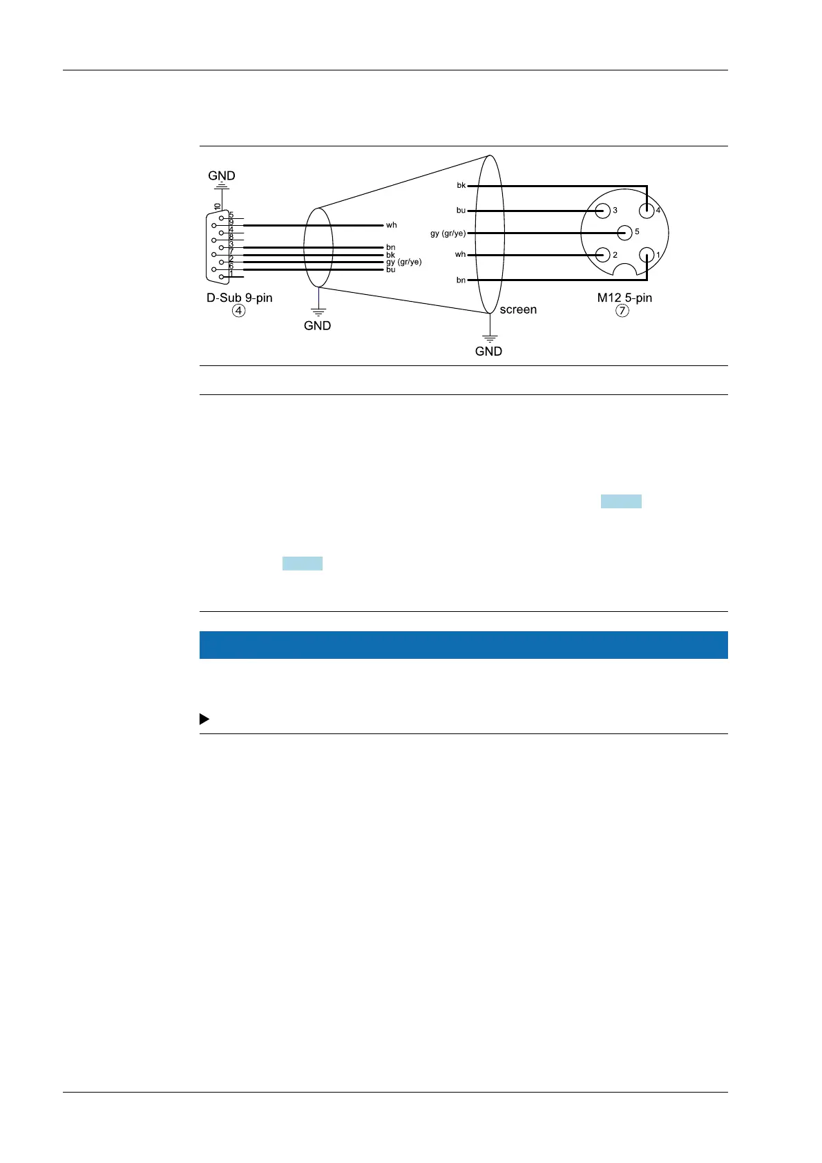
Connection diagram D-Sub 9-pin → M12 5-pin
Note:
There are two types of cable that can be used to connect the PR 5510/05 option
(CANopen interface in the PR 5410) to the first Connexx module.
- PR 6152/10, ../25, and ../40 are pre-assembled cables with an M12 5-pin plug
connector and a D-Sub 9-pin plug connector, see also Chapter
4.6.5.3.
- PR 6152/11, ../26, and ../41 are cables with an M12 5-pin plug connector, to which a
D-Sub 9-pin plug connector with screw connectors can be connected. See also
Chapter 4.6.5.3.
This variant is used, for example, if the cable is to be fed through a cable gland.
NOTICE
Incorrect assignment of the D-Sub plug connector, female.
Destruction of the Connexx module.
The connection diagram shown must be adhered to.
X3 Process Indicator PR 5410 4 Device installation
EN-74 Minebea Intec