B-20
FX Series PLC User's Manual - Data Communication Edition
N:N Network
4 Wiring
4.3 Connection Diagram
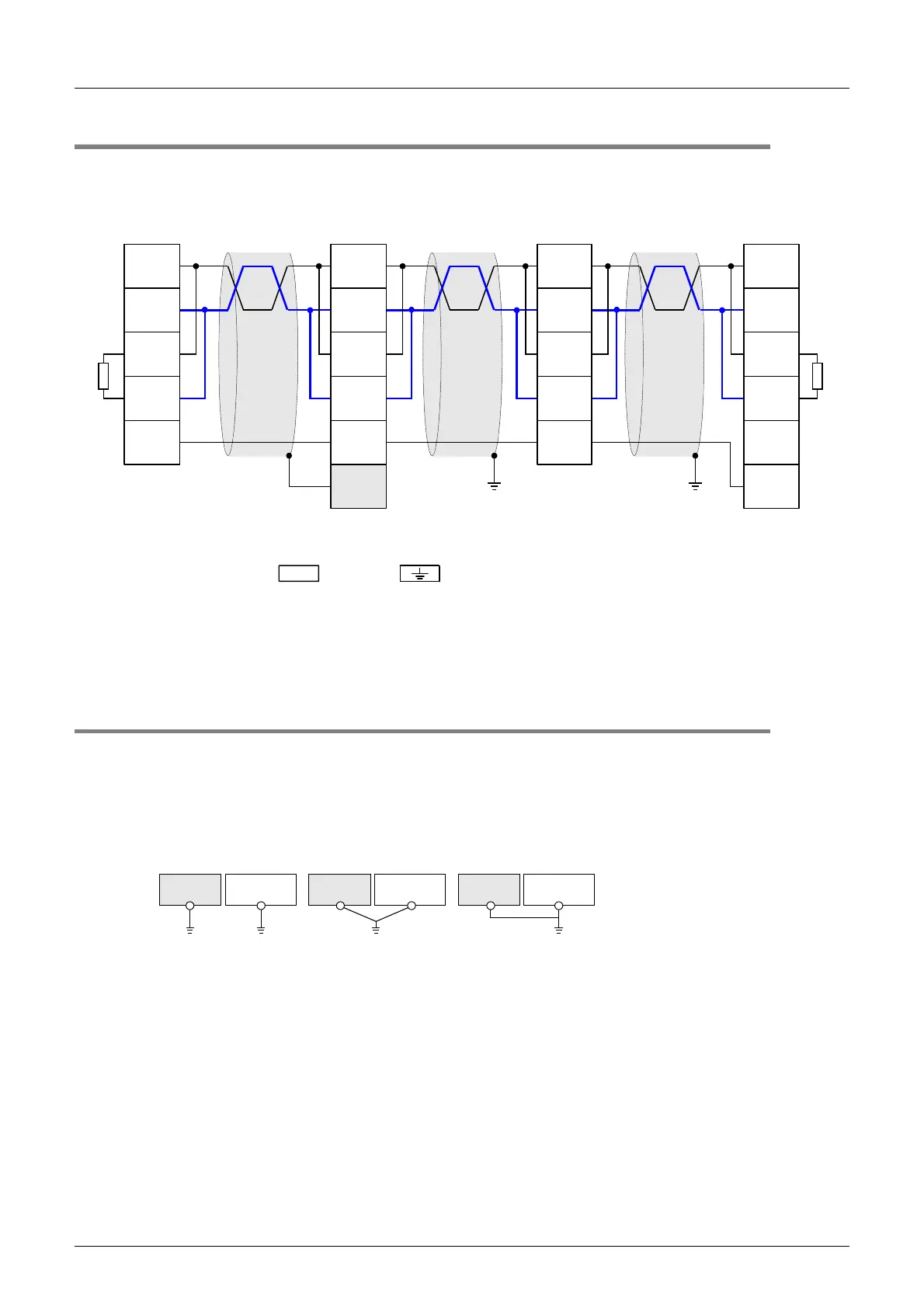
4.3 Connection Diagram
Use one-pair wiring for an N:N Network.
4.4 Grounding
Grounding should be performed as stated below.
• The grounding resistance should be 100Ω or less.
• Independent grounding should be performed for best results.
When independent grounding can not be performed, perform "shared grounding" as shown in the following
figure.
→ For details, refer to the Hardware Edition of each series.
• The grounding wire size should be AWG 14 (2 mm
2
) or larger.
• The grounding point should be close to the PLC, and all grounding wires should be as short as possible.
Terminal
resistor:
110
Ω
Class-D grounding
(resistance: 100
Ω
or less)
*1
Class-D grounding
(resistance: 100
Ω
or less)
*1
FX
2NC
-485ADP
SDA
SDB
RDA
RDB
SG
FX
3U
-485-BD
FX
2N
-485-BD
FX
1N
-485-BD
FX
3U
-485ADP(-MB)
SDA
SDB
RDA
RDB
SG
FX
0N
-485ADP
SDA
SDB
RDA
RDB
LINK
SG
FG
*2
Terminal
resistor:
110
Ω
Communication
equipment in
accordance
RS-485
SDA
SDB
RDA
RDB
LINK
SG
*3 *3
Make sure to perform Class-D grounding to the shield of a twisted pair cable connected to the FX
2N
-485-BD, FX
1N
-485-BD,
FX
3U
-485-BD, FX
2NC
-485-ADP or FX
3U
-485ADP(-MB).
FG
Make sure to connect the terminal to the (grounding) terminal in the PLC requiring Class-D grounding.
If the grounding terminal is not provided in the PLC, perform Class-D grounding directly.
Make sure to provide a terminal resistor at the end of each line.
The FX
3U
-485-BD and FX
3U
-485ADP(-MB) have a built-in terminal resistor. Set the terminal resistor selector switch accordingly.
The FX
0N
-485ADP, FX
2NC
-485ADP, FX
2N
-485-BD and FX
1N
-485-BD are supplied together with terminal resistors.
*2
*1
*3
PLC
Other
equipment
PLC
Other
equipment
PLC
Other
equipment
Shared grounding
Good condition
Common grounding
Not allowed
Independent grounding
Best condition

 Loading...


