C-47
FX Series PLC User's Manual - Data Communication Edition
Parallel Link
9 Troubleshooting
9.5 Checking Absence/Presence of Errors
A
Common Items
B
N:N Network
C
Parallel Link
D
Computer Link
E
Inverter
Communication
F
Non-Protocol
Communication
(RS/RS2 Instruction)
G
Non-Protocol
Communication
(FX
2N
-232IF)
H
Programming
Communication
I
Remote
Maintenance
Apx.
Discontinued
models
3. Presence of VRRD and VRSC instructions (except FX3U and FX3UC PLCs)
Verify that the VRRD and VRSC instructions are not used in the program.
If these instructions are used, delete them, reboot the PLC’s power.
4. Presence of RS instruction (except FX3U and FX3UC PLCs)
Verify that the RS instruction is not used in the program.
If this instruction is used, delete it, reboot the PLC’s power.
5. Presence of RS/RS2 instruction (in FX3U and FX3UC PLCs)
Verify that the RS and RS2 instructions are not being used for the same channel.
If these instructions are used for the same channel, delete them, reboot the PLC’s power.
6. Presence of EXTR instruction (in FX2N and FX2NC PLCs)
Verify that the EXTR instruction is not used in the program.
If this instruction is used, delete it, then reboot the PLC’s power.
7. Presence of IVCK, IVDR, IVRD, IVWR, and IVBWR instructions (in FX3U and FX3UC PLCs)
Verify that the IVCK, IVDR, IVRD, IVWR and IVBWR instructions are not being used for the same channel.
If these instructions are used for the same channel, delete them, reboot the PLC’s power.
9.5 Checking Absence/Presence of Errors
Verify that errors have not occurred in the master station and slave station. Errors can be checked using the
flags shown below.
1. Checking the device M8072
While the parallel link is established, M8072 remains ON.
If M8072 is OFF, an error has occurred in the parallel link setting or communication.
2. Checking the device M8073
If the parallel link is not set correctly, M8073 turns ON.
If M8073 is ON, verify that the master station and slave station are set correctly in sequence programs.
3. Devices for checking link errors
1) Checking the error flags M8063 and M8438 (in the FX3U and FX3UC)
If a communication error occurs in the parallel link, the serial communication error flag turns ON.
When ch1 is used, M8063 turns ON. When ch2 is used in the FX
3U and FX3UC, M8438 turns ON.
When the serial communication error flag turns ON, the error code is stored in D8063 or D8438.
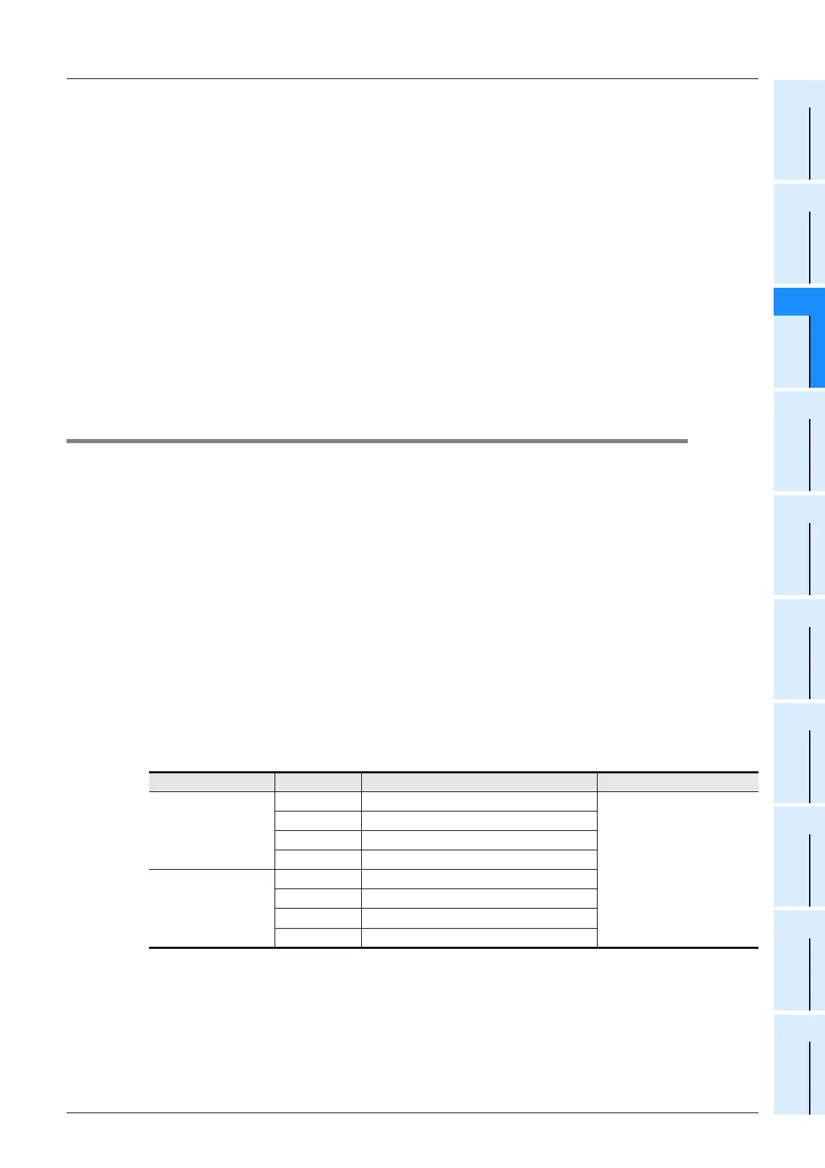
2) Checking the error code
When a communication error occurs in parallel link using ch 1, the error code is stored in D8063.
When a communication error occurs in parallel link using ch 2, the error code is stored in D8438.
The table below shows the details of error codes.
Caution
The devices for checking link errors are not cleared even after communication errors are reset.
They are cleared when the PLC mode is changed from STOP to RUN.
Device Error code Description Action
D8063
0000 No error
Verify that the parallel link
setting programs are set
correctly. Check the wiring
also.
6312 Character error in parallel link
6313 Sum check error in parallel link
6314 Format error in parallel link
D8438
(in FX
3U and FX3UC)
0000 No error
3812 Character error in parallel link
3813 Sum check error in parallel link
3814 Format error in parallel link

 Loading...


