E-25
FX Series PLC User's Manual - Data Communication Edition
Inverter Communication
4 Wiring
4.8 Connection Diagram
A
Common Items
B
N:N Network
C
Parallel Link
D
Computer Link
E
Inverter
Communication
F
Non-Protocol
Communication
(RS/RS2 Instruction)
G
Non-Protocol
Communication
(FX
2N
-232IF)
H
Programming
Communication
I
Remote
Maintenance
Apx.
Discontinued
models
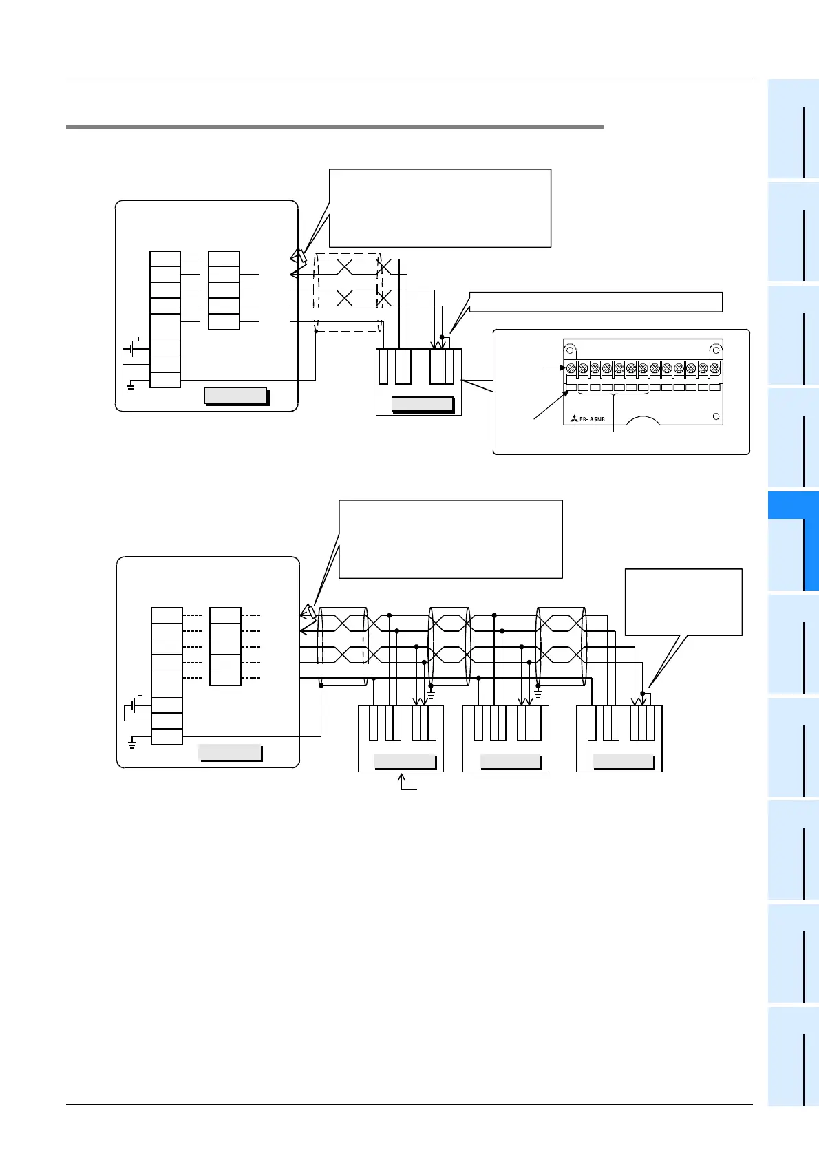
4.8.2 For A500 Series (FR-A5NR)
1. When one inverter is connected
2. When two or more (up to eight) inverters are connected
Connect the terminal resistor connection piece.
Twisted pair cable
(0.3mm
2
or more)
R
D
B
R
D
A
S
D
A
S
D
B
S
G
FR-A5NR
R
D
R
RDA
RDB
SDA
SDB
LINK
SG
24+
24G
RDA
RDB
SDA
SDB
SG
FX
0N
-485ADP
24V
DC
50mA
FG
Class-D grounding
Inverter
PLC
FX
2NC
-485ADP
FX
2N
-485-BD
FX
3U
-485-BD
Terminal
block
Screw size:
M3
Terminal
symbol
Connect them to the
communication unit of the PLC.
Terminal
arrangement
FX
3U
-485ADP(-MB)
Terminal resistor: 110
Ω
• FX
3U
-485-BD and FX
3U
-485ADP(-MB):
Set the built-in selector switch.
• FX
2N
-485-BD and FX
2NC
-485ADP:
Connect a terminal resistor (supplied)
between the RDA and RDB terminals.
SDBSDA RDA RDB RDR
SG A
B
C
0.3mm
2
or more
Twisted pair cable
(0.3mm
2
or more)
....
R
D
B
R
D
A
S
D
A
S
D
B
S
G
FR-A5NR
R
D
R
Inverter
R
D
B
R
D
A
S
D
A
S
D
B
S
G
FR-A5NR
R
D
R
R
D
B
R
D
A
S
D
A
S
D
B
S
G
FR-A5NR
R
D
R
Connect the terminal
resistor connection
piece to the inverter
located furthest
away from the PLC.
Class D
grounding
Class D
grounding
PLC
RDA
RDB
SDA
SDB
LINK
SG
24+
24G
RDA
RDB
SDA
SDB
SG
FX
0N
-485ADP
24V
DC
50mA
FG
Class-D grounding
Inverter Inverter
For the pin arrangement of the connector,
refer to the connection diagram above for one inverter.
0.3mm
2
or more
FX
2NC
-485ADP
FX
2N
-485-BD
FX
3U
-485-BD
FX
3U
-485ADP(-MB)
Terminal resistor: 110
Ω
• FX
3U
-485-BD and FX
3U
-485ADP(-MB):
Set the built-in selector switch.
• FX
2N
-485-BD and FX
2NC
-485ADP:
Connect a terminal resistor (supplied)
between the RDA and RDB terminals.

 Loading...


