B-3
FX Series PLC User's Manual - Data Communication Edition
N:N Network
1 Outline
1.1 Outline of System
A
Common Items
B
N:N Network
C
Parallel Link
D
Computer Link
E
Inverter
Communication
F
Non-Protocol
Communication
(RS/RS2 Instruction)
G
Non-Protocol
Communication
(FX
2N
-232IF)
H
Programming
Communication
I
Remote
Maintenance
Apx.
Discontinued
models
1. Outline
This chapter explains the N:N Network.
1.1 Outline of System
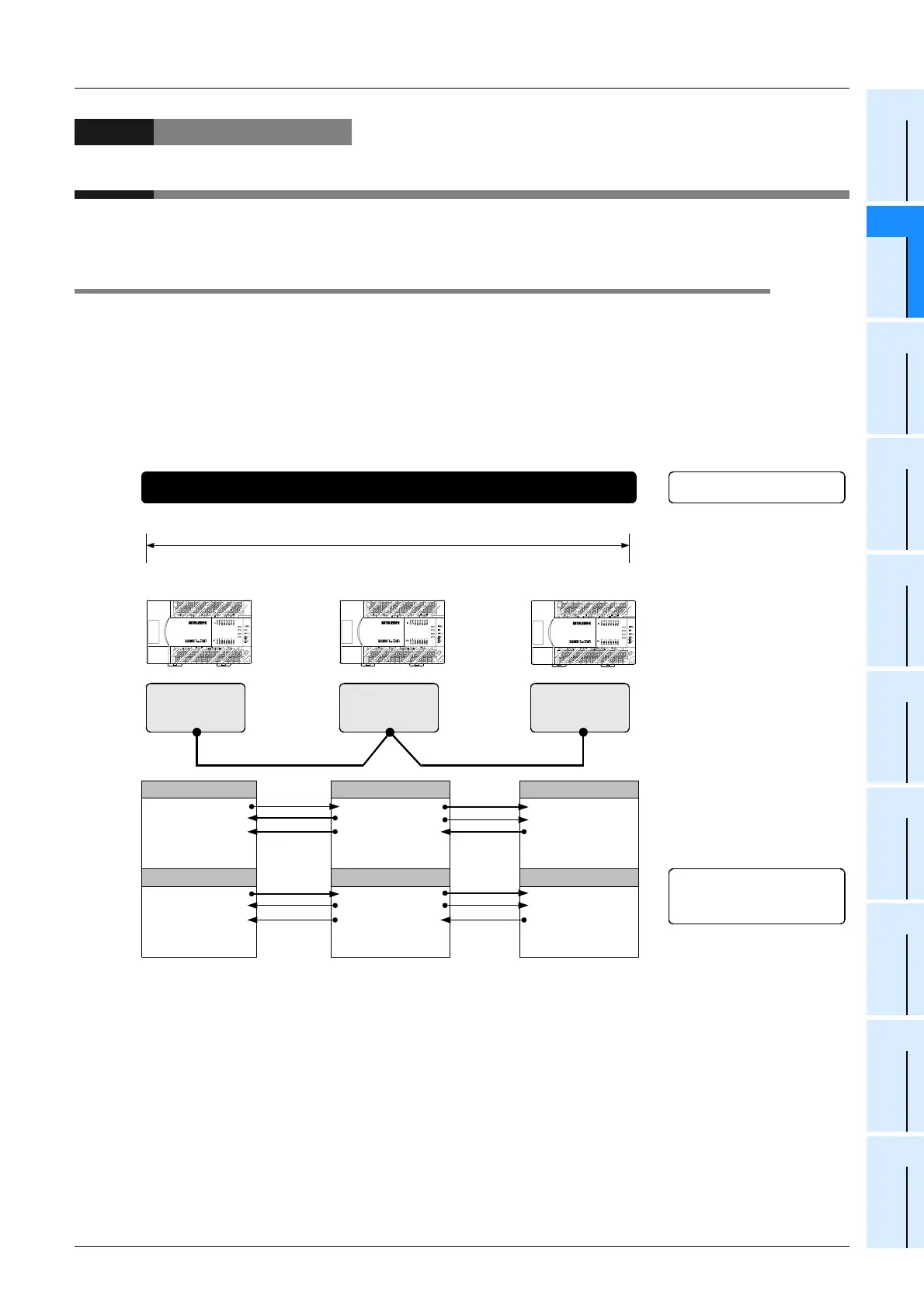
The N:N Network allows connection of up to eight FX PLCs via mutually linked devices through
communication in accordance with RS-485.
1) One of three patterns can be selected according to the number of devices to be linked (except FX
1S and
FX
0N PLCs).
2) Data link is automatically updated among a maximum of eight FX PLCs.
3) The available total extension distance is 500 m (1640' 5") maximum (when only the 485ADP is used in
the configuration).
.......
For selection,
refer to Chapter 3.
Communication
equipment operating
in accordance with
RS-485
Communication
equipment operating
in accordance with
RS-485
Communication
equipment operating
in accordance with
RS-485
FX PLC FX PLC
FX PLC
Master station
Slave station No. 1
Slave station No. 2
500 m (1640' 5") [50 m (164' 0") when 485BD is included]
.......
8 units
Number of linked units
Total extension distance
For the specifications,
refer to Chapter 2.
Bit devices
M1000 to M1063
M1064 to M1127
M1128 to M1191
M1448 to M1511
Word devices
D0 to D7
D10 to D17
D20 to D27
D70 to D77
Bit devices
M1000 to M1063
M1064 to M1127
M1128 to M1191
M1448 to M1511
Word devices
D0 to D7
D10 to D17
D20 to D27
D70 to D77
Bit devices
M1000 to M1063
M1064 to M1127
M1128 to M1191
M1448 to M1511
Word devices
D0 to D7
D10 to D17
D20 to D27
D70 to D77
.......
The number of linked devices
can be selected among three
patterns.
For details, refer to Chapter 2
.......
For wiring,
refer to Chapter 4.
The link information can be
monitored in the master
station and all slave stations.
+++
Transfer
direction
Transfer
direction
.......
To check applicable PLC
models, refer to Section 1.3.
The figure above shows the maximum number of linked devices. There are differences in the specifications and
limitations depending on the selected link pattern and FX Series.
Important points and reference
chapter/section
System
.......
... ...
... ...
... ...

 Loading...


